Synchronous Motion Servo-control of Biaxial Cross Coupling Based on Intelligence Fusion Strategy
2013-09-17XIONGXiansheng
XIONG Xiansheng
Intellectualization Branch,Chongqing Tengsheng Building Engineering Group Co.,Ltd,Chongqing 404000,China
Industrial computed tomography(ICT)is a sort of effective nondestructive-testing means,and it is widely applied to lots of fields such as industrial production,aerospace and safety monitoring,etc.With the continuous expanding of application fields,it presented higher performance demand in running speed,positioning and tracking accuracy as well as synchronization precision,etc for synchronization motion of ray source-detector biaxial position,and its effectiveness and veracity of data collection directly influences the imaging quality of image[1-3].Aimed at the control puzzle of servo synchronous motion between ray source axis and detector axis in the scanning process of Industrial computed tomography system,the following explored the related problems of control strategy for biaxial synchronous motion.
1.Influence analysis of control tracking accuracy
Industrial computed tomography system mainly consists of mechanical scanning,ray source detecting,scanning image reconstruction and auxiliary subsystem.In which,the mechanical scanning subsystem is a sort of numerical control scanning stage,and it is in charge of detecting relative motion between object and ray source detecting subsystem.The form of scanning motion can be divided as translation,rotation and hierarchy motion.The performance of scanning motion directly affects the effectiveness and accuracy of collection data for industrial computed tomography system,and finally it affects the imaging quality.It is one of main motion form of scanning motion to the synchronous motion between ray source axis and detector axis.For computed tomography scanning,it demands the ray source and ray detector to be able synchronously to arrive at the des-ignated tomography position as soon as possible.Therefore the research of synchronous motion in fact is that it researches on motion control of biaxial position synchronization based on synchronous servo system.In the actual motion process,the synchronous performance suffers from lots of influence factors such as load unbalance,friction disturbance and uncertainty factors etc.Especially when the scanning speed is enhanced,the change of friction moment,interference impact moment,and moment of inertia is very easy to make biaxial synchronization error and single axis tracking error.With the sudden change of setting speed,it is easy to result from being enlarged in system overshoot,increasing in adjusting time,and even produce unstable.In all the influence factors,the uncertainty is the main key factor.Aimed at the characteristic of controlled object and feature of synchronous motion of biaxial position,the research of synchronous motion control owns important significance for enhancing canning precision of industrial computed tomography and imaging quality.
2.Improvement of synchronous motion control method
The classical synchronization control owns four sorts of control methods such as master-slave synchronization, parallelsynchronization, cross-coupling synchronization and virtual main-axis synchronization.In which,the slave motor will have to follow the main motor.But the interference suffered by slave motor is impossible to be fed back to main motor,its trajectory is even deviated more far away than the expected,and thereby it is inadvisable for high accurate control.Each motor of parallel synchronous control has itself independent motion control loop,and unconnected each other.As long as each motor can strictly follow the command trajectory motion,and then it can realize the motion synchronization.But in the actual application,because it is not the same in load characteristic and suffered disturbance and independent of each other for each self loop,so the position of each motor could produce more deviation,and therefore it is difficult to ensure the control precision and performance of synchronous motion.The synchronous control method of cross coupling is based on parallel synchronous control,and through the comparison of speed or position output signal for two motors it takes difference as the additional feedback signal respectively to compensate the speed of two motors,therefore it can make two motors obtain better synchronous performance.The structure of control system is shown as in Fig.1.The control method of virtual main-axis synchronization is based on master-slave synchronous control,and it makes drive moment of slave axis feed back to forward channel of main axis controller so as to realize the parameter coupling feedback among master-slave axis.Due to the main axis being virtual set,it would be more flexible for parameter configuration.The control of deviation coupling is an improving method,and it not only keeps the characteristic such as high precision of cross coupling control,but also it can overcome some shortcomings.The deviation control is that it compares the deviation of both,and then it takes the deviation signal to be added so as to compensate the controlled object[4-6].

Fig.1 Cross coupling synchronization control
3.Control strategy of cross coupling based on intelligence fusion
In the biaxial position servo system,the research object only deals with the motion control of ray resource axis and detector axis,and it is very suitable to adopt the synchronous control of cross coupling control system.There are lots of control strategies that can be supplied to select,but there still are lots of puzzle needed to be solved.For example,NN control needs definite experiment samples.Due to the influence of uncertainty,it is hard to obtain the experiment samples from the known experience and aforehand experiment.Because of the method limitation,it is also difficult to realize effective control generally.The expert control system is based on the knowledge,and because it is difficult to extract the characteristic information to express the characteristic information and build the maturity repository.Therefore the expert control system(ES)is also difficult to realize the synchronous control of cross coupling con-trol system.The hominine control experience can carry through the summarization and description by means of hominine language,it can be depicted to fuzzy linguistic language by means of fuzzy set in fuzzy mathematics,and also it can be realized by the sentence of“IF condition THEN action”.But because the uncertainty factors are too much,the general fuzzy control is unnecessarily a good choice for synchronous control of cross coupling.The basic property of HSIC(Human Simulated Intelligent Control)is to simulate the control behavior of control expert.Therefore its control algorithm is a multimodal control,and the material method is to execute alternate use among multimodal control.Such a property makes the contradictions of control quality demand are perfectly harmonized for control system.It is maybe a sort of more wise choice.But as a result of the parameters adjusted being too much,the parameter tuning is very complex,therefore it is not able to be selected.In this paper,it takes the control strategy of cross coupling based on intelligence fusion,it can integrate the superiority of various control strategies such as ES,HSIC,etc,and it also includes PID.It is worth to pay attention to the limitation of PID control.
The control model of Fig.1 can be equivalent as Fig.2,in which,e(t)=r(t)-y(t)),r(t),y(t),u(t)is respectively the deviation,input and output of the process,and output of the controller.The typical response is shown as in Fig.3.In which,e,ec represents respectively the process deviation and its change rate,and therefore it can be divided into different time section such as OA,AB,BC,CD and DE.

Fig.2 PID control model
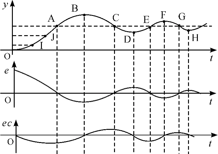
Fig.3 Typical response curve of 2-order system
The following discusses the influence of each parameter of PID controller for steady and dynamic performance.The function of proportional,integral and differential unit is respectively to reduce the system deviation,to eliminate steady error of the system and to reflect the change trend of deviation signal.The control parameter KP,KIand KDshould be appropriately selected,and the too big or small value would result in bad control effect.Combined with the response curve in Fig.3,the tuning principle of PID-parameter would be as below.Here the paper takes only subsection OA(e>0,ec<0)as an example,under the action of unit-step signal it is considered as the key transition phase from static state to dynamic state,and after that it is gradually turned to steady state.Owing to the influence of system inertia,this subsection curve decides only to assume ascending in certain incline.In this phase,when e > 0,the e assumes reducing trend,and ec < 0,the absolute value of deviation e must assume reducing trend.For obtaining better control performance,the gain control should be adopted in the subsection OA.If the fixed proportion control mode is adopted then when the output reaches the steady value it is impossible to hold steady value and certainly it will bring the overshoot because of the system itself inertia.In order to make the system response speed rapidness and not to bring the great overshoot,the subsection OA should be divided as three subsections to carry through analysis,namely that is respectively OI,IJ and JK.In the subsection OI,the deviation value is larger,it can take larger gain coefficient KPand less gain KDso as to expedite the response speed and prevent instantly biggish value of starting deviation.In order to prevent integral saturation,the integral action should be canceled(gain KI=0)or reduce the integral action so as to avoid the system response bringing larger overshoot.In the subsection IJ,the gain coefficients,such as KP,KIand KD,should not be taken as too large value to avoid the system producing overshoot.It should take less KIand middle KPas well as KDso as to insure the response speed of the system.And in the subsection JA,it has better development trend to reduce the deviation,we should reduce the KPand enlarge KIto avoid the oscillation around the set value.In order to enhance the anti-jamming performance,generally it is better to take middle size value for KD.According the above principle,it can analyze the subsection AB(e < 0,ec < 0),BC(e<0,ec>0),CD(e>0,ec>0)and DE(e>0,ec<0).
Thereafter the situation of each time section is similar to the above situation.Here it is not any more to repeat.The puzzle of parameter tuning is that once the system performance is changed or goes beyond the anticipated bound,whether or not the system can automatically tune the parameter of PID,and retune the parameter of PID to obtain better control effect.Therefore the paper adopts the synchronous motion servo-control strategy of biaxial cross coupling based on intelligence fusion.The most outstanding advantages are that it is better in real time performance,faster in system response speed,and high in tracking control.
4.Research on simulation experiment
4.1.Control algorithm of simulation
Based on intelligence fusion,the basic algorithm can be summarized as two sorts of dynamic characteristic pattern.① Pattern of proportion and half derivation(PH-D control pattern),the execution condition is that if e·˙e≥0 and e+˙e≠0 then PH-D control pattern.② Pattern of half open-loop(HO control pattern),the execution condition is that if e·˙e≤0 or e=˙e=0 then HO control pattern.The algorithm of prototype in the human simulated intelligent controller is the following.

Where u,Kp,k,e,˙e and em,irespectively represents the control output,proportion coefficient,constraint coefficient,system deviation,change rate of system deviation and the value of the ithdeviation peak.After the expert knowledge,practice experience,operating skill and adjusting technique of operators are fused in the algorithm,and the detailed control algorithm can be summarized by structured English description method as the following.


4.2.Model parameter of simulation
In the experiment simulation,the parameter of each tache is set as the following,armature resistance R=0.4Ω,d-q axes saturated inductance L=5.12 mH,amplification coefficient of three-phase PWM inverter KPWM= 30,average time of losing control τPWM=0,001 67 s,time constant of currentloop filtering τi=0.002 s,current feedback coefficient Ki=0,072,time constant of closed-loop rotation speed filtering τν=0.01 s,feedback coefficient of rotation speed Kν=0.006 7,position feedback coefficient is 1,moment of inertia J=0.014 3 kgm2.
4.3.Simulation result
1)Control pattern of PID with feed-forward control
Under the precondition of two motors being the same and no anti-interference measure,it adopts the control pattern of PID with feed-forward control to acturalize the tracking control.At the time t=2 s,the motor 1 is joined by a 5 Nm step disturbance,and the motor 2 is joined by a 8 Nm step disturbance.Under different control method,the response curve of position tracking and synchronization is respectively shown as in Fig.4 ~6.Through comparison for Fig.4~6,it can be seen that whatever the master-slave synchronization control or the parallel synchronous control,the error of position tracking and synchroni-zation is relatively larger than the cross coupling synchronization control,and specially,if it is suffered from disturbance then the error is rather large.The simulation demonstrated that the cross coupling synchronization control is better in control tracking quality than master-slave and parallel synchronization control.

Fig.4 Master-slave synchronization control
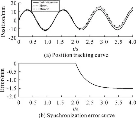
Fig.5 Parallel synchronous control
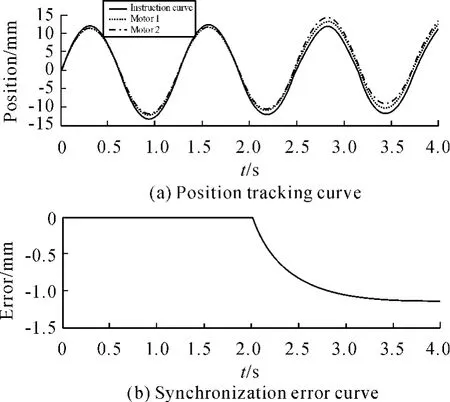
Fig.6 Cross coupling synchronization control
2)Controlpattern based on intelligence fusion strategy
For being more convenient in comparison,here it takes the following transfer function of controlled object as an example.

Here the simulation gives three response curves under unit step input.The curve 1 shows the response without controller,and the steady error is rather large.The curve 2 shows the response joined in PID controller with KP=3,KI=0.4 and KD=0.363,and it can be seen that the steady error is eliminated but there is in overshoot.The curve 3 shows the response joined in a controller based on intelligence fusion strategy,and it can be seen that the steady error is eliminated,and at the same time it ensures the tuning speediness.Although the experiment is rather simple,but it demonstrates the feasibility based on intelligence fusion control strategy.
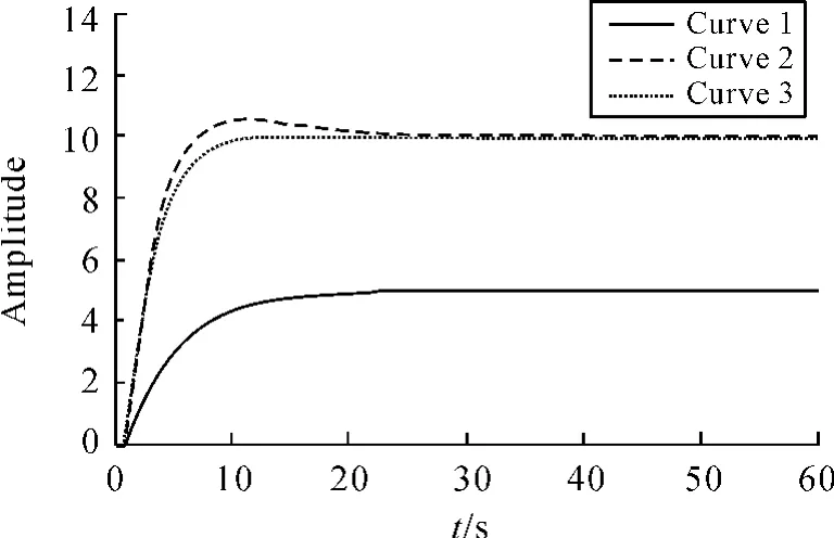
Fig.7 Effect comparison of PID and intelligence control
5.Conclusions
The above discussed several sorts of synchronous control strategy and its improving strategy,through simulation,it makes the performance comparison,and the simulation results demonstrated that the cross coupling control excels the master-slave and parallel control.If the intelligence fusion control strategy is adopted then the control tracking effect would be better.
[1] SUN Yaxin.Research on synchronous control of scanning motion for industrial CT[D].Chongqing:Chongqing U-niversity,2009.
[2] TIAN Dapeng,WU Yunjie,LIU Xiaodong.Synthesis methods of high precision motor servo system control[J].ELECTRIC MACHINES AND CONTROL,2010,14(7):66-74.
[3] FUJIMOTO H,KAWAMURA Y.Perfect tracking control based on multi-rate feed-forward control with generalized sampling periods[J].IEEE Transactions on Industrial E-lectronics,2001,48(3):636-644.
[4] Dong Sun.Position Synchronization of Multiple Motion Axis with Adaptive Coupling Control[J].Automatica,2003,39:997-1005.
[5] ZHAO Ximei,GUO Qing-ding.Zero Phase Adaptive Robust Cross Coupling Control for NC Machine Multiple Linked Servo Motor[J].Proceedings of the CSEE,28(12):129-133.
[6] Teng Fulin,Hu Yuwen,Huang Wenxin,et al.Position Tracking Error in AC Servo Systems[J].Journal of Nanjing University of Aeronautics & Astronautics,2008,40(6):815-819.
杂志排行
机床与液压的其它文章
- Wavelet Analysis Fault Information and Realization in Virtual Instrument
- Design of Experimental System for Measurement of Cam Profile
- Finite Element Analysis for a New Friction-based Limited-slip Differential Housing
- Precision Measurement of Series Motor Housing Based on CMM
- Decoupling Control Algorithm of Online Self-tuning Based on DRNN
- Simulation and Optimization Analysis of Circuit Breaker Operating Mechanism
