机电控制带式无级变速器的改进PID速比控制与仿真
2013-08-22吴俊毅
程 越 ,吴俊毅,李 鑫,2
1.重庆理工大学 a.汽车零部件制造及检测技术教育部重点实验室;b.车辆工程学院,重庆 400054;2.重庆市科学技术研究院,重庆 401123
1.Introduction
This article will introduce a novel electro-mechanical continuously variable transmission which is different from traditional continuously variable transmission in structure,working principle and control method.Research shows that in a metal belt CVT’s energy loss,the hydraulic system accounts for about 60%while the metal belt’s frictional transmission accounts for about only 30%[1].Because of the EM-CVT which has a pure Electro-Mechanical component and control method abandons the low efficient hydraulic system,It simplifies the structure with a significant degree and its cost has fallen by more than 30%.Also,EM-CVT improves the reliability and the efficiency of the whole drive train.
This article analyzes the structure and principle of EM-CVT,establishes speed ratio model,clamping force model and adjustable-speed motor model,studies on the speed ratio control strategy of EM-CVT,improves the conventional PID speed ratio control algorithm.In the end,the improved PID speed ratio control algorithm is simulated and analyzed in Matlab/Simulink.
2.Structural characteristics and working principle of EM-CVT
The main body of the EM-CVT is still the metal belt and pulley.The biggest difference between EM-CVT and other CVTs is that the adjustable-speed and pressure mechanisms use a pure electro-mechanical adjustable-speed mechanism which is composed of a motor,a gear reducer and a screw nut mechanism and a pressure system which are composed of a pair of disc springs instead of the traditional hydraulic system.Its working principle is shown in Fig.1.
The adjustable-speed motor pulls the primary moving cone disk to move to right or left through a gear reducer and a screw nut mechanism to achieve changes of metal belt effective working radius to achieve the purpose of changing speed ratio[2].Disc springs provide clamping force for moving cone disk through baffle disk to clamp the metal belt.The metal belt transmits the engine torque from primary cone disk group to secondary cone disk group through frictional force and outputs the torque from secondary cone disk group.

Fig.1 The principle diagram of EM-CVT
3.Mathematical modeling of EM-CVT speed ratio control system
3.1.EM-CVT speed ratio model
EM-CVT speed ratio is generally defined as the secondary pulley speed divided by primary pulley speed.If not considering the slip between the cone disk group and metal belt,the speed ratio can be expressed as follows.

Where Rsis the effective working radius of secondary pulley,Rpis the effective working radius of primary pulley.
When the speed ratio of EM-CVT is varying,since the elastic deformation of metal belt is very small,the length of the metal belt can be regarded as constant value.According to the geometric relationship[ 3],

The approximate calculation formula between the effective working radius of primary pulley and speed ratio can be obtained by simultaneous Eq.(1),(2)and(3).

Where icvt=,L is the length of the metal belt and d is the center distance of EM-CVT.
According to the principle of speed ratio change of EM-CVT,the effective working radius change rate of primary pulley is decided by axial movement speed of active cone disk,it is as follows[4].

Where d x is the axial movement speed of primary cone disk,βis the angle between the generatrix and vertical of the cone disk,n is the motor speed,i is the gear ratio of reducer and P is the lead of screw.
3.2.EM – CVT’s adjustable-speed motor model
The adjustable-speed motor of EM-CVT is a DC motor.According to the DC motor voltage balance equation and dynamic equation,a mathematical model of motor can be created as follows[5].

Where R is the DC motor resistor,T is the time constant,e is the back-EMFof motor,U is the DCmotor control voltage,Jdis the moment of inertia of the motor,Tlis the motor load and Tdis the electromagnetic torque generated by motor.
3.3.The clamping force model of EM-CVT
The pressure system of EM-CVT provides a clamping force for the primary and secondary cone disk by a pair of disc springs.As shown in Fig.2,the axial movement of primary cone disk makes the amount of deformation of disc spring vary within a certain range which is 3.8 ~6.2 mm.Clamping force produced by disc spring floats near 22 500 N,the amount of change is very small.So the clamping force,of primary and secondary pulley of EM-CVT can be regarded as a constant value.

Fig.2 Disc spring’s working curve
4.EM-CVT speed ratio control strategy
EM-CVT’s core mission is to determine the target speed ratio according to engine speed,opening degree of throttle as well as the current speed and make actual speed ratio track target speed ratio realtime accurately by the speed ratio controller.
Optimum economic curve can be obtained by curve fitting of speeds of the lowest fuel consumption rate with each opening degree of throttle.Similarly,optimum power curve can be obtained,as shown in Fig.3.

Fig.3 Optimum economic and power curve
The relationship among EM-CVT target speed ratio,engine speed and vehicle speed is as follows[6].

where i is the EM-CVT target ratio,r is the wheel radius,neis the engine target speed,i0is the final drive ratio and v is the vehicle speed.
The one-to-one correspondence between engine speed and opening degree of throttle of optimum economy or power of automotive can be obtained and shown below by the optimum economic or power curve based on the above.

The optimum economic or power target speed ratio for EM-CVT can be obtained and shown below by simultaneous Eq.(9),(10)and(11).

According to formula(12)and(13),the corresponding target speed ratio for EM-CVT is calculated under different speeds and opening degrees of throttle.The results are shown in Fig.4 and 5.

Fig.4 Economic target speed ratio

Fig.5 Power target speed ratio
5.The PID control algorithm for EM-CVT speed ratio
5.1.Conventional PID control algorithm
According to the target speed ratio obtained by speed ratio control strategy,the speed ratio controller can make the actual speed ratio track the target speed ratio real-time accurately to enable engine to work in the economic or power curve to achieve the economic or power performance of vehicle.
PID control algorithm composed of proportional,integral and differential control is a very effective and mature control way.It is a linear control algorithm,the control deviation e(t)can be obtained by the difference between the target value r(t)and the actual output value c(t).

To use deviation e(t)to constitute control volume by linear combination in accordance with the relationship among the proportional,integral and the differential to control the controlled object,the control law is as follows[7].

It is well known that microcomputer control is a sampling control,the amount of deviation e(t)can be calculated by the current sampling time,so the conventional PID control algorithm must be discretized.Digital PID controller equation which is shown below can be obtained by using a series of sampling time points kT to take place of continuoustime t and using cumulative sum to take place of integral and using difference to take place of differential.

where Kpis the proportional coefficient,KIis the integral coefficient,KDis the differential coefficient and e(k)is the deviation value of the kth sampling output.
EM-CVT speed ratio PID control principle is that when there is a deviation e(k)which is the difference between the actual speed ratio iact(k)and target speed ratio itar(k),PID controller adjust and magnify the deviation e(k)quickly into a voltage signal u(k)and put the signal into adjustable-speed motor.The motor drives the primary cone disk to have an axial movement through a reducer to change the pulley’s working radius so that the speed ratio can be changed.The flow chart of the speed ratio is shown in Fig.6[8].Since the roads which people drive on are complex and changeable and the driving habits of drivers are different,EM-CVT speed ratio control methods in different conditions are different.Thus conventional PID control with fixed parameters can’t make the speed ratio normally changeable,and even cause failure control.The problems mentioned above can be solved by introducing the improved PID control algorithm.

Fig.6 The PID control algorithm flow diagram of EM-CVT speed ratio
5.2.Integral separation PID control algorithm
There are some requirements which are small overshoot,no static error,fast system response and avoiding oscillation for speed ratio controller in EMCVT speed ratio control system.The deviation e(k)of conventional PID controller output will have a dramatic change in a short period of time when the EMCVT speed ratio control system treat some special conditions which are large change rates of speed ratio such as vehicle starting,rapid acceleration,rapid deceleration and emergency brake.This will result in integral accumulation of PID arithmetic and make controlling quantity calculated over the limits of controlling quantity of the maximum adjusting range of implementing agencies and finally cause the system to overshoot,and even lead to a large oscillation of the system.This is not allowed absolutely in EM-CVT control system.
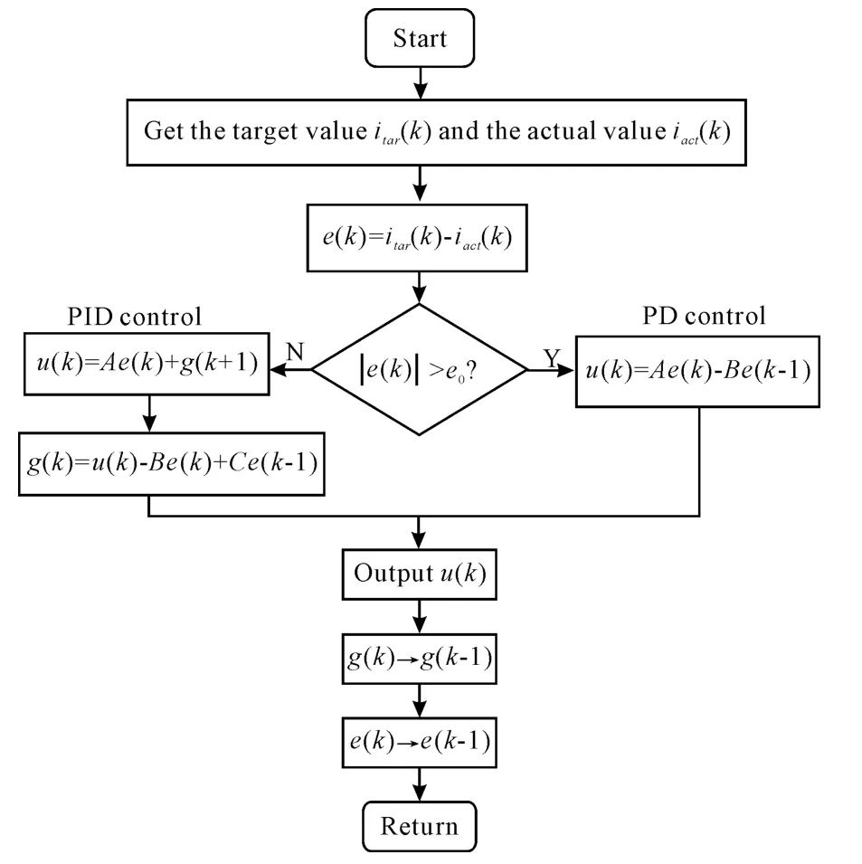
Integral separation PID control algorithm can not only avoid overshoot and oscillation when the speed ratio deviation is large,but also eliminate the static error when the deviation is small.Integral separation PID principle is that canceling the integral link to avoid reducing stability of system and increasing overshoot under integral impact when the speed ratio deviation e(k)is large,adding integral link in order to eliminate static error and improve control accuracy when the actual speed ratio is close to the target speed ratio.It means that EM-CVT speed ratio controller only have proportional and differential control due to a large deviation e(k)’s existence when a large speed ratio change rate happens and adding integral impact when the deviation e(k)access a range of some values.This is good for improving the dynamic characteristics and eliminating the static error.The integral separation PID control algorithm flow diagram is shown in Fig.7:

Fig.7 The integral separation PID control algorithm flow diagram
The specific steps are as follows[9].
To set a threshold of deviationεartificially and ε>0 according to the actual situation of EM-CVT,the speed ratio deviation is()e k=itar(k)-iact(k).
1)Adopting PD control method can avoid generating excessive overshoot and make the system have a faster response when the speed ratio deviation’s absolute value.
2)Adopting PID control method can ensure a accurate control precision when the speed ratio deviation’s absolute value .
Integral separation PID control algorithm can be expressed as follows.

whereβ is a weight coefficient in the above formula.Integral separation of PID can be achieved by the coefficient.The method of setting the value of the coefficient is to makeβ=1,adopt PID control when|e(t)|<εand makeβ=0,adopt PD control when|e(t)|>ε.
5.3.Differential forward PID control algorithm
The mutation of target speed ratio may cause an oscillation of actual speed ratio and bring an impact on control system due to auto target speed ratio’s changes with changes in the driving environment.Introducing the differential forward PID control algorithm is to avoid an impact of speed ratio control which is brought by step change of target speed ratio.
The characteristic of the differential forward PID control algorithm is that only to differentiate the actual speed ratio iact(k)and not to differentiate the deviation e(k).So,the change of actual speed ratio iact(k)is relatively mild when changing the target speed ratio itar(k)so that eliminating the controlled object’s influence which is brought by the rapid changes of the target speed ratio itar(k).
The specific method of the differential forward PID control algorithm is that changing the differential term from the deviation e(k)to the actual speed ratio iact(k)-iact(k-1)so that making the differential link avoid negative impact which is generated by changes of the target ratio.Meanwhile,first order low pass filter(1/γTDs+1)can be introduced into the differential link in order to filter out high frequency interference signals.Eventually,the transfer function of the differential term becomes as follows.

where TDis the differential time constant andγ is the filtering coefficient.
To make inverse laplace transformation,differential operation and discretization on the formula(18)in order to make the formula suitable for the digital applications expression[10].

where uD(k)is the differential component of PID controller which is at k moment,uD(k-1)is the differential component of PID controller which is at(k-1)moment and the differential forward PID control algorithm can be expressed as follows.

5.4.Improved PID control algorithm
The discrete expression for the improved PID control algorithm which is based on the integral separation and differential forward PID control algorithm is as follows.

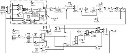
The control block diagram of improved PID control algorithm for EM-CVT speed ratio is shown in Fig.8.

Fig.8 The control block diagram of improved PID control algorithm for EM-CVT speed ratio
EM-CVT is controlled by the improved PID speed ratio control algorithm ensures that actual speed ratio of auto can avoid hysteresis and oscillation in the case of the large change rate of the target ratio and eliminate the negative impact which is brought to speed ratio control by the rapid changes of the target speed ratio and ensure EM-CVT to change the speed ratio stably and reliably and enhance the adaptability of the system.
6.The simulation and result analysis of EM-CVT speed ratio control
6.1.The simulation of EM-CVT speed ratio control
The computer simulation model of EM-CVT is established based on Matlab/Simulink.To simulate the speed ratio controller of EM-CVT with the conventional PID speed ratio control algorithm and the improved PID speed ratio control algorithm at the same time to verify the correctness of the model and examine the PID speed ratio tracking performance of the conventional PID control algorithm and improved PID control algorithm through comparing simulation results.
The computer simulation model of EM-CVT which is established according to the mathematical model introduced above is shown in Fig.9.The main parameters of the model are shown in Tab.1.The input of the model is EM-CVT target speed ratio.A deviation is formed between the target speed ratio and actual speed ratio which are measured by system.The deviation is amplified and adjusted to a PWM signal of adjustable-speed motor through speed ratio controller and PWM generator.Then the adjustablespeed motor model transforms the PWM signal into a motor speed signal.Finally,EM-CVT actual speed ratio can be got from the motor speed signal through speed ratio model.Wherein,the pulse width modulation is equivalent to a delay link in the control system,take 1/20 000 s time as a pulse width period.The step changes of target speed ratio of EM-CVT simulate extreme cases such as the big change rate of speed ratio(large deviation)and the zero change rate of speed ratio(little deviation)in the system to examine the performance of two speed ratio control algorithms.Wherein,the largest target speed ratio is 2.2,the minimum target speed ratio is 0.5 and the variation period is for 50 s.

Tab.1 The main parameters of EM-CVT

Fig.9 EM-CVT speed ratio model
6.2.Simulation result analysis
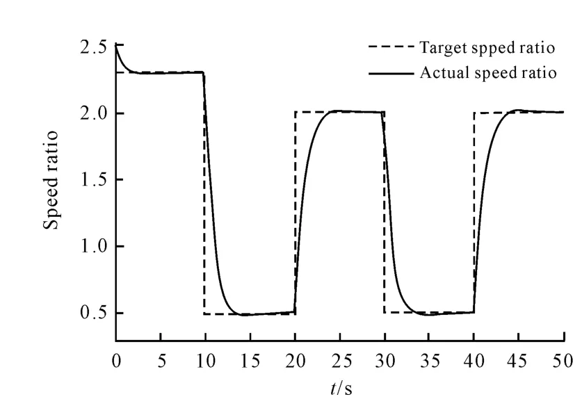
The simulation results are shown in Fig.10 and Fig.11.Fig.10 is an EM-CVT step changing target speed ratio tracking simulation curve of the conventional PID speed ratio control algorithm.Fig.11 is an EM-CVT step changing target speed ratio tracking simulation curve of the improved PID speed ratio control algorithm.What can be observed obviously is that the actual speed ratio can’t track the target speed ratio well and it generates overshoot,oscillation and lag obviously and it spends long time to revert with the conventional PID speed ratio control algorithm when the change rate of target speed ratio is big.Wherein,when the target speed ratio is near 0.5,the actual speed ratio has a serious overshoot,oscillation and lag.The actual speed ratio is at a constant value which is the lower limit of speed ratio at this time due to the upper and lower limit of the EMCVT speed ratio are limited by its mechanical structure(the parts of overshoot are limited by its mechanical structure).The actual speed ratio can track the target speed ratio quickly and accurately but not to have an overshoot,oscillation or lag with the improved PID speed ratio control algorithm.The results prove that the improved PID ratio control algorithm possesses good tracking performance and control effect.

Fig.10 The simulation curve of conventional PID speed ratio control
7.Conclusions

Fig.11 The simulation curve of improved PID speed ratio control
The control performance of the vehicle equipped with EM-CVT has been significantly improved by improving the conventional PID speed ratio control algorithm when the vehicle treats some special conditions which are large change rate of the speed ratio such as vehicle starting,rapid acceleration,rapid deceleration and emergency brake.The vehicle can change the speed ratio stably and reliably.
This article analyses structure and principle of the EM-CVT,establishes the EM-CVT speed ratio model,clamping force model and speed motor model,studies on the speed ratio control strategy of EMCVT,improves the conventional PID speed ratio control algorithm.In the end,the improved PID speed ratio control algorithm is simulated and analyzed in Matlab/Simulink.Simulation results show the correctness of the model which has been established above and verify the good control effectiveness and superiority of the improved PID speed ratio control algorithm.
[1] ZHANG Lanchun,CHANG Siqin.Theoretical analysis and test verification of all-electrically regulated CVT[J].Automotive Engineering,2009,8(31):751-755.
[2] YANG Xinhua.Electro-mechanical continuously variable transmission control system and control strategies[D].Wuhan:Huazhong University of Science and Technology,2010.
[3] GONG Xiangyu,ZHANG Lei.Integrated ratio control for vehicles with CVT based on ADVISOR[J].Computer Simulation,2007,24(1):258-261.
[4] LUO Shunzhi,CHENG Yue,LI Xin.Control of tansmission ratio for machinery and electronic control metal belt and its simulation[J].Journal of Chongqing University of Technology:Natural Science,2011,25(8):14-20.
[5] HUANG Lipei.Motor control[M].Beijing:Tsinghua U-niversity Press,2003.
[6] YU Zhisheng.Automobile theory[M].Beijing:China Machine Press,1996.
[7] JIN Guangle.Research on control system and experiment of electronic mechnical continuously variable transmission[D].Shenyang:Northeastern University,2009.
[8] Heera L,Chulsoo K,Talchol K,et al.CVT ratio control algorithm by considering powertrain response lag[C]//Transmission and Driveline Symposium,March 8-11,2004.Detroit,Michigan:SAE World Congress,2004.
[9] WEN Ming,HUANG Miaohua.Design of continuously variable transmission PIDspeed ratio controller[J].Beijing Automotive Engineering,2009(2):13-16.
[10] LIU Yan.Research and experiment on control system and control strategy of EM-CVT[D].Shenyang:Northeastern University,2009.
