Study on Inertial Response Performance of A Micro Electrical Switch for Fuze
2013-07-25Wei-rongNIE,Zhan-wenXI,Wei-qingXUE等
Study on Inertial Response Performance of A Micro Electrical Switch for Fuze
The design,modeling,and simulation of a micro electrical switch for fuze are presented.It consists of spring-mass system with zigzag slot in mass,latching and electrical connection mechanism and movement-limit mechanism.The switch keeps off-state until it is subjected to an acceleration when fuze is launched normally.The acceleration is simulated as half-sine pulse with specif i c amplitude and duration.The dynamics model of the switch is studied.Based on zigzag slot in mass,the methods used for recognizing acceleration load are established and analyzed according to the dynamics theory.Two typical half-sine accelerations are loaded on the switch in simulation.The simulation results are in accordance with those of theoretical analysis.The inertial response characteristics of the switch can ensure that the fuze power supply and circuit are connected safely and reliably.
CopyrightⒸ2013,China Ordnance Society.Production and hosting by Elsevier B.V.All rights reserved.
Micro electrical switch;Fuze;Zigzag slot;Inertial response
1.Introduction
MEMS electrical switch has the advantages of small volume and smart response,so it is promising for power supply controlling system application in varied forms.Farrington et al.[1]proposed a hybrid electrical switch which can deliver signif i cant reductions in switching elements,cabling,cost and power consumption.Chui[2]put forward MEMS electrical switches used for interferometric modulator,which may form the row or column select functions for the display.Deylitz et al.[3]invented an electrical switch which includes a locking device.Verma and Kaushik[4]studied RF MEMS capacitive switch based on a f i xed-f i xed beam structure,which is designed to achieve low actuation voltage and good reliability. Baghchehsaraei et al.[5]presented a waveguide SPST switch based on a MEMS reconf i gurable surface and its RF performances are superior attributed to the high level of processing circuit integration.Guo et al.[6]designed a MEMS acceleration switch with an easy-latching/diff i cult-releasing latching mechanism,in which all the contacts and support beams are separated from the proof mass to prevent the contacts from opening due to the impact resulting from the rebound or vibration once the switch is latched.Kim et al.[7]devised an acceleration switch capable of increasing the threshold acceleration,in which the comb drive actuators are used in the design to tune the threshold acceleration.
In recent years,MEMS technology also has been integrated closely with advanced weapon system due to the smart requirements for weapon system[8].Robinson et al.[9-11] proposed a MEMS safety and arming mechanism and carried outthedemolaunchandballistictests.Jingetal.comeupwitha MEMS safety mechanism of fuze in small caliber rocket round according to the amplitude and duration of acceleration.It can identify the launching environment and perform actions by theZ-shaped teeth,but it is not suitable for the fuze in medium and largecaliberammunition[12].Liuetal.[13]designedaMEMS zigzagslotwhichisappliedtothesafetyandarmingmechanism in small caliber projectile fuze of Objective Individual Combat Weapon(OICW),but it cannot be used in the fuze in medium and large caliber projectile.
This paper proposes a MEMS electrical switch for the fuzes in medium and large caliber projectiles,which is excited by inertial acceleration.The switch responds to acceleration amplitude as well as duration.It can be used for the initiation of fuze power supply.It provides more safety functions when it works in fuze special working environment.
2.Device structure and function
The switch proposed in this paper is a mechanical inertial electrical switch.The switch is normally in off-state.It is actuated to be in on-state only when fuze is launched smoothly, whileitstillholdsanoff-stateinanyaccidentalfallingimpact.It is designed with the performance of reacting to launching accelerationquicklyandreliably.Anditalsoneedstokeeptheonstate in order to ensure that the power and circuit work continuously.It consists of three parts,a spring-mass system with zigzag slot in mass,a latching and electrical connection mechanism,and a movement-limit mechanism.Fig.1 shows the structure diagram of the MEMS inertial electrical switch.
The switch has the functions of acceleration response,acceleration amplitude and pulse width recognition,which is actuated by an inertial force.The MEMS spring-mass system is mainly used to detect acceleration undergone by fuze.When fuze is undergoing an acceleration,the mass will be moved. The zigzag slot in mass has damping effect on mass movement,which can be used reasonably to distinguish the fuze launching acceleration from accident falling impact[14].
Thelatchingandelectricalconnectionmechanismalsoreacts to acceleration load,and it can be impacted by moving mass. When the latching and electrical connection mechanism transforms from off-state to on-state,it can keep latching by its resilience.The movement-limit mechanism,including side board and stoppers,is used to prevent the proof mass from producing a large lateral jumping and limit the Y-axis displacement of the proof mass.
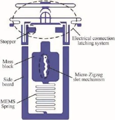
Fig.1.Schematic diagram of MEMS electrical switch.
3.Model and theoretical analysis
3.1.Spring-mass system with zigzag slot
The spring-mass system with zigzag slot is shown in Fig.2.The coordinate system and force analysis of the micro zigzag slot colliding with a f i xed anchor are shown in Fig.3.
The mass is subjected to 4 forces,i.e.inertial force FR, spring force FS,counterforce FCand frictional force Ff.The inertial force FRand the spring force FSare obvious.The mass collides with the f i xed anchor when it is moving along the Y-axis direction.Therefore the f i xed anchor generates a counterforce FCon the zigzag slot in mass.The frictional force Ffexists between the f i xed anchor and the zigzag slot.
All these forces could be represented in the same coordinate system.In order to simplify the analysis,two assumptions on collision are proposed:(a)The solid collision model is used between the mass and the f i xed anchor,and the collision contact time is very short;(b)The collision between the mass and the f i xed anchor is deemed as the collision of ideal cylindrical surface with the plane.
Based on these assumptions,the velocity of proof mass changes little and the collision counterforce FCis very large compared with the spring force FS,the inertia force FRand the friction force Ff.Therefore,these forces are ignorable when the collision occurs.Thus,the movement differential equation in Y direction of proof mass is as follows:

where m is the mass;k is the stiffness of the spring;δ is the amount of deformation of spring;and a is the acceleration. The acceleration model in this paper is simplif i ed to a half-sine curve,that is a=Agsin ωt,where Agis the acceleration amplitude in m/s2,ω is the angular frequency of the half-sine pulse,t ranges from 0 to 3 ms.
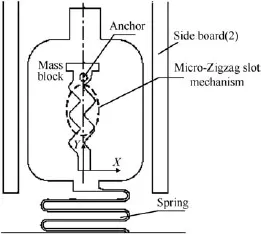
Fig.2.Schematic diagram of planar micro zigzag slot.
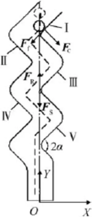
Fig.3.Force analysis model.
As shown in Fig.3,the whole movement of proof mass can be broken into f i ve segments,i.e.Segment I,Segment II, Segment III,Segment IV and Segment V.Each segment of movement equations is similar to the Eq.(1).Analysis of Segment I is shown in Fig.3.The initial boundary conditions are
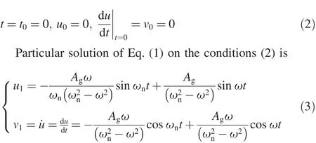
where u1and v1are the displacement and velocity of the proof-mass,respectively.ωn=s the natural frequency of the spring-mass system.
In order to analyze the mass movement in Segment II,it is necessary to know the boundary conditions at this time. Therefore,its velocity and position after the fi rst collision between the fi xed anchor and zigzag slot must be analyzed carefully.So thenew parameters are given,k'is the stiffness of the spring,ωr= is the natural frequency in Segment II movement,v1is the initial velocity of the mass and v'1is the velocity after fi rst collision.
The movement of proof mass approximately complies with the ref l ection principle in collision dynamics,that is,the directions of the velocity before and after collision are symmetric about the normal of slot surface where collisions occur. So the velocity direction is related to the dip of the slot surface.For simplicity,the f i xed anchor is treated as a movable cylindrical pin,and the mass is immovable in accordance with the principles of the relative movement,as shown in Fig.4.
For α=45°,according to the above assumptions,the velocity before the f i rst collision is the velocity in Y direction, that is,v1y=v1.The velocity after collision is v'1=βv1sin 2α, where β is the collision coeff i cient of restitution.β ranges from 0.2 to 0.6 on the basis of Ref.[15].
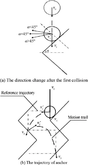
Fig.4.The velocity and trajectory analysis after the f i rst collision.
The particular solution of Segment II of movement equations can be obtained on the above boundary conditions.
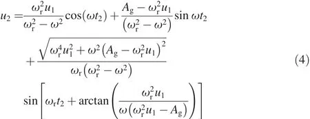
where t2is a time variable,which the range of values is the time period in Segment II movement.So the velocity of the proof mass can be derived by the following equation

As for the following segments of movement,the displacement and velocity can be deduced in the same way.In order to get the particular solution of movement equation in Segment III,IVand V,the previous collisions before this segment must be analyzed carefully to get the boundary conditions for movement equation of this segment.The total displacement ofthe proof mass is u=u1+u2+...+u5.The time it takes to move is t=t1+t2+...+t5.
3.2.Latching and electrical connection mechanism
The latching and electrical connection mechanism also responds to acceleration and is impacted by proof mass.It can keep latching by its resilience once it is actuated to be in onstate.It is a two-stage electrical connection mechanism and is able to make the switch hold a conducting state during the entire process of closing and connecting.
The response of the latching and electrical connection mechanism to the acceleration load includes two stages.In the fi rst stage,the movable contact shown in Fig.5 is subjected to an inertial force when fuze is launched with acceleration A, while the proof mass is also subjected to an inertial force.But the movable contact moves in Y direction more slowly than the proof mass due to its less mass.In the second stage,the proof mass contacts and pushes the movable contact to move.As for the process of switch closing,the movable contact touches with the L-shaped latching beam at fi rst,and then the L-shaped latching beam is gradually opened due to the impact from the movable contact.Therefore,the movable contact can get across L-shaped latching beam and keeps moving along the Y direction.The following movement of movable contact will cause the switch to be latched.The movable contact touches the top contact before separating from the L-shaped beam.The conducting state in the entire process won’t be interrupted. When the proof mass is blocked by the stoppers,the movable contact stops moving forward and backtracks due to its elasticity.The movable contact keeps contact with L-shaped latching beam because it restores the original shape after the movable contact get through.This is the latching state of the switch that is kept by resistance of L-shaped latching beam.
4.Results and simulation analysis
4.1.Theoretical calculation
Acceleration excitation A,shown in Fig.6(a),has the amplitude of 3000 g and the duration of 3 ms,which is used to simulate the setback shock produced in the process of fuze launching.Acceleration excitation B,shown in Fig.6(b),is used to simulate the fuze accident falling impact on hard ground[16].The amplitude of excitation B is 15,000 g,while the duration is 300 μs.
Acceleration excitation A and B are exerted on the spring-mass system with zigzag slot.The displacement and velocity of mass under excitation A and B can be calculated, shown in Fig.7(a)and(b).
In Fig.7(a),there are two curves,SaandSb,which represent the displacements of the mass,respectively.In Fig.7(b),VaandVbindicate the velocities of the mass,respectively.It can be seen from Fig.7 that the motion stroke of the mass under excitation B is less than that under excitation A,which means the moving distance of the mass under excitation B is shorter than that under excitation A.The velocity of proof mass can’t increase continuously until the zigzag slot has no inf l uence on the mass.
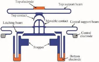
Fig.5.Schematic diagram of latching and electrical connection mechanism.

Fig.6.Acceleration excitation.
4.2.Finite element analysis
Furthermore,the movement of the spring-mass system with zigzag slot is analyzed by f i nite element analysis software ANSYS.The displacement and velocity curves under excitation A and B are obtained,as shown in Fig.8(a)and(b).
Fig.8 shows that the maximum displacement in Y-axis under excitation A is 723 μm,while is 387 μm under excitation B.The displacement and velocity curves shown in Fig.8 are basically coordinated with those in Fig.7.
Due to a short duration time of falling impact load,the proof-mass with the micro zigzag slot is pulled back to theinitial position by the spring before moving to the def i ned position along the Y direction.Therefore,the switch is always held in the off-state.While the duration of smoothly launching acceleration is longer,the proof mass could produce an enough large displacement to push the latching mechanism to the position of contacting and latching.
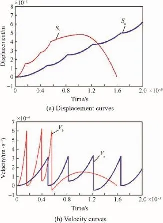
Fig.7.Theoretical calculation results.
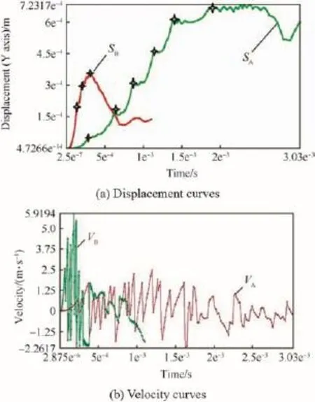
Fig.8.Finite element simulation results.
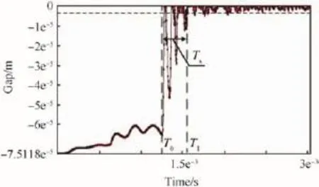
Fig.9.The gap between the top contact and the movable contact when the switch closes.
The MEMS switch is made of electroformed nickel,which can be manufactured by the improved UV-LIGA technology [17,18].The two main electrodes of the switch are the top electrode and the movable electrode.So the gap between the top contact and the movable contact is signif i cant for the characteristics of the switch closed-state.The simulation result of the gap is shown in Fig.9.
Fig.9 shows that the time from the start to the end of the entire closing process of the latching and electrical connection mechanism is nearly coincident.After these small vibrations in the closure process,the gap value is near to zero,which shows that the switch is closed and is kept in a stable state.
5.Conclusion
A MEMS inertial electrical switch based on spring-proof mass was proposed.The switch has the capability of identifying the smooth launching acceleration from the accident falling acceleration.Since the zigzag slot is embedded into the spring-mass system,the switch can identify the acceleration amplitude and the pulse duration.The overall size of the switch is 5.5 mm×4 mm.The proof mass has a displacement of over 700 μm when it undergoes an acceleration with amplitude of 3000 g and duration of 3 ms.But when it is subjected to the acceleration with amplitude of 15,000 g and duration of 0.3 ms,it only has a displacement of less than 400 μm.There exists an obvious difference in displacement when the switch is subjected to the two typical accelerations. The inertial response characteristics of the switch can ensure the fuze power supply and circuit work safely and reliably.As for displacement and velocity of spring-mass system,the theoretical calculation model is deduced segment by segment in zigzag slot,and the results are basically coordinated with those of numerical analysis model.It is very meaningful for the parameter optimization of the switch structure when it is adapted to different acceleration.
[1]Farrington N,Porter G,Radhakrishnan S,Bazzaz HH,Subramanya V, Fainman Y,et al.Helios:a hybrid electrical/optical switch architecture for modular data centers.ACM SIGCOMM Comput Commun Rev 2011;41(4):339-50.
[2]Chui C.Interferometric modulator array with integrated MEMS electrical switches.U.S.Patent 20120256819.2012.10.11.
[3]Deylitz E,Gehrke B,Lamoth P,Schmidt M.Electrical switch.U.S. Patent 20120222945.2012.9.6.
[4]Verma D,Kaushik A.Analysis of RF MEMS capacitive switch basedonaf i xed-f i xedbeamstructure.IntJEngResAppl 2012;2(5):391-4.
[5]Baghchehsaraei Z,Shah U,A˚berg J,Stemme G,Oberhammer J. Millimeter-waveSPSTwaveguideswitchbasedonreconf i gu; rable MEMS surface.In:2013 IEEE MTT-S International Microwave Symposium,IMS 2013,2-7 June 2013,Seattle,WA, USA 2013.
[6]Guo ZY,Zhao QC,Lin LT,Ding HT,Liu XS,Cui J,et al.A acceleration switch with a robust latching mechanism and cylindrical contacts.J Micromech Microeng 2010;20(5):1-7.
[7]Kim HS,Jang YH,Kim YK,Kim JM.MEMS acceleration switch capableofincreasingthresholdacceleration.ElectrLett 2012;48(25):1614-6.
[8]Niu LJ,Shi KL,Zhao X,Zhai R.Application of MEMS on fuzes.J Detect Contr 2008;30(6):54-9[in Chinese].
[9]Robinson CH,Wood RH,Gelak MR,Hoang TQ.Air-powered electromechanical fuze for submunition grenades.U.S.Patent 7849798. 2010.12.14.
[10]Robinson CH,Wood RH,Gelak MR,Hoang TQ,Smith GL.Ultraminiature electro-mechanical safety and arming device.U.S.Patent 8276515.2012.10.2.
[11]Robinson CH,Wood RH,Bayba A,Hollingsworth D.MEMS safety and arming device for OICW.In:NDIA Small Arms Conference in Little Rock 2001.pp.1-22.
[12]Jing H,Niu LJ,Song YQ.The method of design and simulation of MEMS S&AD for fuse in small-caliber grenade.J Projectiles,Rockets, Missiles and Guidance 2010;30(2):129-32.
[13]Liu CQ,Lou WZ,Zhang LF,Lv YJ.Parametric research on micro-zigzag slot mechanism in OICW.Key Eng Mater 2011;483:699-704.
[14]Tan YJ.Theoretical study on Zigzag slot of arming mechanism.Nanjing University of Science and Technology;2008[in Chinese].
[15]Wang H,Chen HJ.Analysis of compound inertia braking safety and arming device.J Detect Contr 2007;29(1):32-5[in Chinese].
[16]Fuze Design Manual Editorial Group.Fuze design manual.Beijing: National Defense Industry Press;1978[in Chinese].
[17]Nie WR,Xi ZW,Li QL.Process simulation and static characteristic simulation analysis of MEMS-based safety and arming device.J Nanjing Univ Sci Technol 2010;34(2):166-9[in Chinese].
[18]Du LQ,Jia SF,Nie WR,Wang QJ.Fabrication of fuze micro-electromechanicalsystemsafetydevice.ChinJMechEng 2011;24(5):836-41[in Chinese].
Wei-rong NIE*,Zhan-wen XI,Wei-qing XUE,Zhi-jian ZHOU
School of Mechanical Engineering,Nanjing University of Science and Technology,Nanjing 210094,China
1 July 2013;revised 21 August 2013;accepted 16 October 2013 Available online 6 December 2013
*Corresponding author.
E-mail address:niewrhappy@163.com(W.R.NIE).
Peer review under responsibility of China Ordnance Society
Production and hosting by Elsevier
2214-9147/$-see front matter CopyrightⒸ2013,China Ordnance Society.Production and hosting by Elsevier B.V.All rights reserved. http://dx.doi.org/10.1016/j.dt.2013.11.001
杂志排行
Defence Technology的其它文章
- Effect of Hardfacing Consumables on Ballistic Performance of Q&T Steel Joints
- Study on Multi-objective Optimization of Airbag Landing Attenuation System for Heavy Airdrop
- Dynamic Fracture Behaviors of Selected Aluminum Alloys Under Three-point Bending
- Experimental Research on the Propagation Process of Continuous Rotating Detonation Wave
- Rough Sets Probabilistic Data Association Algorithm and its Application in Multi-target Tracking
- Analysis of Micro-scale Flame Structure of AP/HTPB Base Bleed Propellant Combustion
