Control Method on Adaptive Abrasive Belt Grinding of Pipe Socket Weld
2013-03-09ZHANGMingdeWANGXinglong
ZHANG Mingde,WANG Xinglong
Mechanical Engineering Institute,Chongqing University of Technology,Chongqing 400054,China
Control Method on Adaptive Abrasive Belt Grinding of Pipe Socket Weld
ZHANG Mingde*,WANG Xinglong
Mechanical Engineering Institute,Chongqing University of Technology,Chongqing 400054,China
For the automatic grinding problem of pipe socket weld,welding geometry model is established and tool calculation and controlling method of processing quality is proposed in this paper.It can use the adaptive process control method of grinding weld and do the machining experiments.Experiments indicate that this method can effectively solve the problems such as overcut,the lack of cutting which occurred in the process of grinding and the problem of controlling grinding quality of pipe weld.
surface,modeling,stress,adaptive machine
Achievement Transfer Program of Institutions of Higher Education in Chongqing(kjzh11217),Scientific and technological project of Chongqing Science&Technology Commission(cstc2012gg-yyjs70006)
*ZHANG Mingde,Associate Professor.E-mail:zmd@
cqut.edu.cn
1.Introduction
Pipe socket weld mainly refers to weld joint which can connect with pipes by welding way.It is mainly used for connecting with boiler tubes and large water pipes.Currently welding method is manual welding,and it is poor quality.Surface finishing and to ensure the weld width and height are the requirements of weld grinding weld.No hurting the parent metal is the one of the requirements of weld grinding,too.The machining method of pipe socket weld is artificial buffing at present.Its disadvantages are low efficiency,poor working environment and big working strength and so on.Using numerical control equipment is the development trend of modern industry.At present there is no such equipment used for the weld pipe.Building grinding geometry model and calculating processing cutter data are the main problems to solve.It realizes automatically adapt to grinding for weld joint of having weld defects.
2.Weld geometry model
Intersecting line of branch and main pipe translates weld height by the pipe axis direction as border on the top of weld.The curve that circle projected onto main pipe by the pipe axis direction as border on the down of weld.The circle’sRis the sum of branch pipe radius and the weld width.The surface which is scanned along with border lines that act as the guide lines is the weld surface,as follows Fig.1.
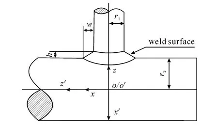
Fig.1 Weld geometry model
In Fig.1,r1is the radius of branch pipe,andr2is the radius of main pipe,as well as,r2>r1.The axis lines of the branch pipe and main pipe are plane intersecting lines,The angle between them is α.Coordinate systemsAandA'are established.The coordinate system’s origin O located in the branch pipe ax-is,and theO'located in the main pipe axis.The two points are superposition.The angle between the axis zand axisz'is α.Coordinate systemA'is that coordinate systemsAare rotated 90 degrees round the axisy.The transformational matrix is obtained as follows:

Setting a space pointPin coordinate systemsAandA',their coordinates are(x',y',z')and(x,y,z)respectively.Their interconnections is obtained as follows:

The equation of branch pipe cylinder in coordinate systemsAis obtained as follows:

The equation of main pipe cylinder in coordinate systemsA'is obtained as follows:

The equation of intersecting line of branch and main pipe can be got from Eqs.(2)~(4)as follows:
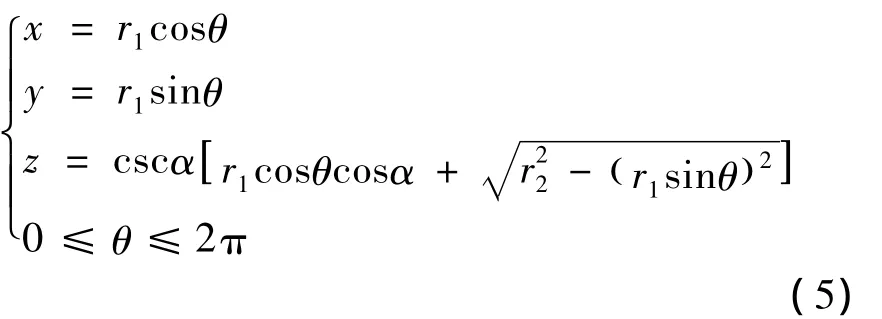
The surface equationS1can be got from Eqs.(2)~(5)as follows:
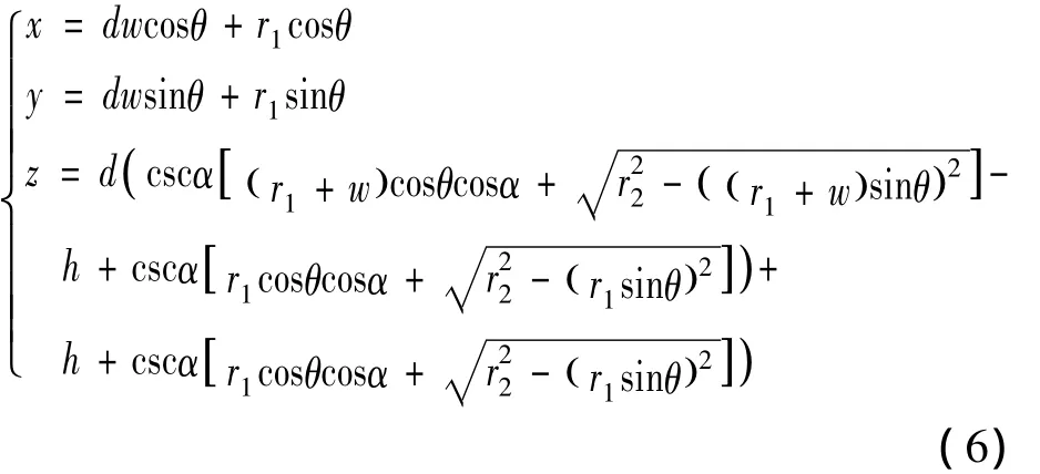
his weld bead height,wis weld width,when the branch pipe and main pipe are perpendicular,α=90,

3.The calculation of NC cutter data
The weld surface isS1,The equation of weld surface isr=r(l,θ).ThekN,which is principal curvature of cutter-contact on theS1,is obtained as follows:

In the formula:E、F、GandL、M、Nstand for respectively the first second fundamental quantity and the second fundamental quantity at cutter-contact of contact surface.
The direction of principal curvature at cuttercontact of contact surfaceS1isrt=dl/dθ,it is obtained as follows:

Contact wheel is rotatedAdegrees round the axisX.It makes sure that direction of principal curvature of cutter-contact keeps pace with axis direction of contact wheel of abrasive belt.Contact state of cutting tool and workpiece is the best,and the best processing efficiency is very high.
From Eq.(9),it can getA,as follows:

the unit normal vector of machining surface:

Contact wheel is rotatedBdegrees round the axisY.It makes sure that normal direction of contact point keeps pace with the direction of support of the abrasive belt wheel.
From Eq.(11),it can getB,as follows:

Determine the scope of the processing.The calculations of processing starting positiontsand end positionteuse the tangent position of contact wheel and tube wall.It makes sure that contact wheel doesn’t impact the branch and main pipe.As follows the Fig.2;Ris the radius of contact wheel.
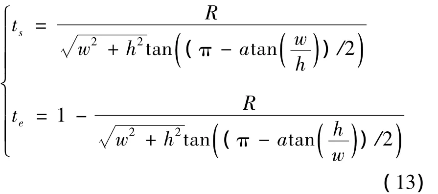
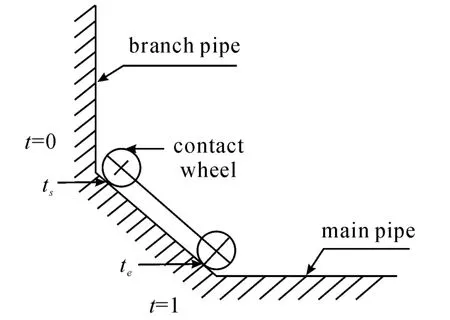
Fig.2 Starting position tsand end position te
Determine the machining array pitch.The size of the array pitch is closely related to the accuracy and efficiency of surface machining.The bigger array pitch,the poor accuracy surface machining;on the contrary,the more overcrowding array pitch,the more machining time.So it should seek a reasonable calculation method of array pitch,it makes the array pitch as large as possible under ensuring the accuracy.
Scallop height isHand array pitch isD.The relationship betweenHandDis obtained as follows:

If the maximum allowable residual height is εH,Dis obtained as follows:

kbis the normal curvature of machining surface on the direction of grinding feed.
Determine the feeding step length.The feeding step length is the distance of the two adjacent Cutter-Contacts.Because the tool path can be regarded as a collection of discrete cutter location data.It needs to change the cutting tool path discretization.The discretization is not arbitrary segmentation,but it should be discrete according to the machining accuracy.To specify the linear approximation error limit ε,when the linear approximation error|δt|<ε,as follows:

So feeding step lengthLcan be obtained as follows:

kfis the normal curvature of machining surface on the direction of grinding feed during interpolation;
Cutting tool path calculation process of surface processing can be expressed simply as follows:
The calculation formula of tool center point:

rcis the vector of tool center point,rpis the vector of processing contact pointPon the surface,Rcis tool radius,as follows Fig.3:
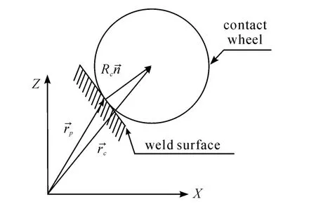
Fig.3 Calculation of tool center point
Equation also can be written as the form of components:

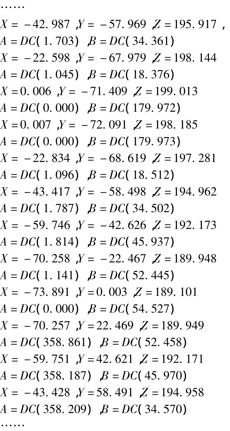
According to the above formula,it can generate NC programs,as follows:
4.Self-adaptation control
It depends on that pipe welding technology are mostly manual welding,and the weld quality of manual welding is not good,weld joint may be the irregular shape.Major Defectives are that there is ecess solder joints,the welding is discontinuous as follows Fig.4,the angle of welding is too big,there is a big bump.It leads to the low machining efficiency,and have a bad effect on machining quality.It cannot reach our ideal requirements as follows Fig.5.
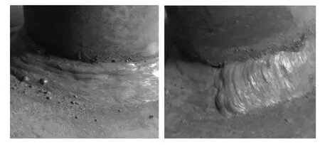
Fig.4 Defectives of manual welding
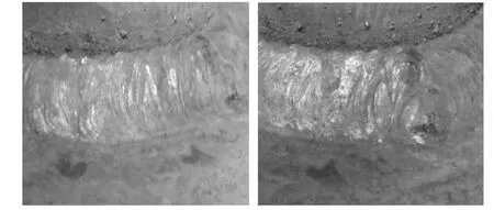
Fig.5 Defectives of manual welding
If it is machined strictly according to the calculated CL data of the theoretical molded surface,it will unable to complete the curved surface machining.In order to automatically adapt to various defectives appearing in the welding,it uses the floating grinding with position feedback mechanism to grind in this paper.Floating grinding mechanism automatically adapts to the irregular shape of the weld joint.As the same time,linear displacement detection device fixed on the floating mechanism has the function of grinding state feedback.It puts measuring displacement into PID controller,and then it uses results from PID controller to control grinding pressure.Finally it can realize automatic adaptive grinding weld.
Based on the above issues,design scheme as follows.The position of the grinding head floating mechanism is zero when the grinding is beginning. When grinding head floating mechanism is stretching,it is positive displacement.Cylinder elongation increasing leads to the contact pressure on the surface of the grinding and abrasive belt to reduce at this time.When grinding head floating mechanism is compressing,it is negative displacement.Cylinder elongation decreasing leads to the contact pressure on the surface of the grinding and abrasive belt to increase at this time.The established mathematical model can be obtained as follows:
Pressure of abrasive belt grinding affects the quantity of grindingZwis material-removal rate[volume(mm3)/time(s)],when it is the axial feed (horizontal),

vwis work speed(m/s),apis depth of cut(mm),fais the axial feed(mm/r),Z'wis the standard (relatively)material removal rate[volume(mm3)/ time(s)·limit(mm)],Bis the width of abrasive belt(mm).
The selection of grinding parameters depends largely on the characteristics of the grinding material.
Reference to the relationship between the grinding material removal rate and cutting force,it can get the relationship between the normal force of permanent removal of abrasive belt grindingFnand the material removal rate of unit widthZ'w,as follows:

Fn0is slipping brush stop,the critical value of normal force at the beginning of the cutting,Δwis material removal rate under the given force,

5.Analysis of experimental and summaries
Through adaptive control,it can realize the optimization of grinding quality of the weld surface and the productive design requirements.It can ensure the weld thickness,achieve smooth over between pipe and weld,increase efficiency and improve the working environment.Fig.6、Fig.7 show no using the adaptive control grinding;Fig.8 shows using the adaptive control grinding.
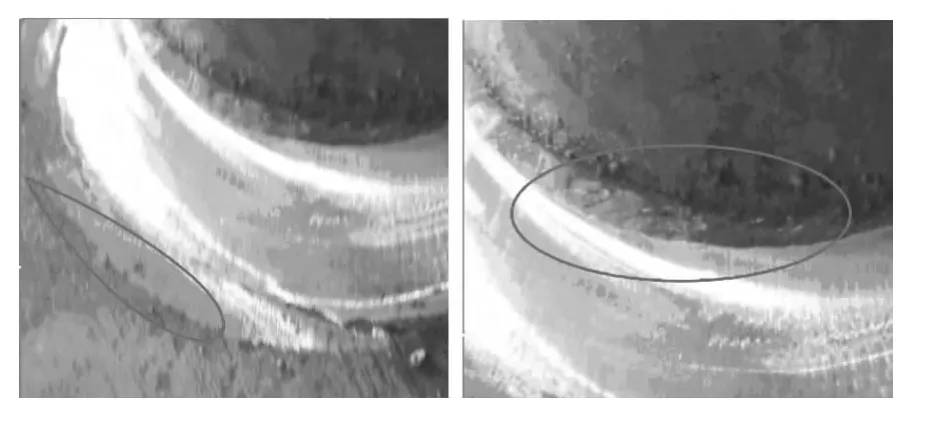
Fig.6 No using the adaptive control grinding
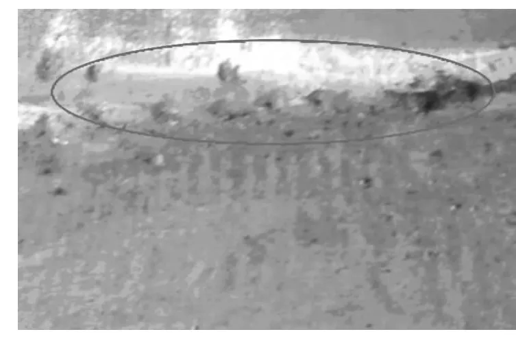
Fig.7 No using the adaptive control grinding
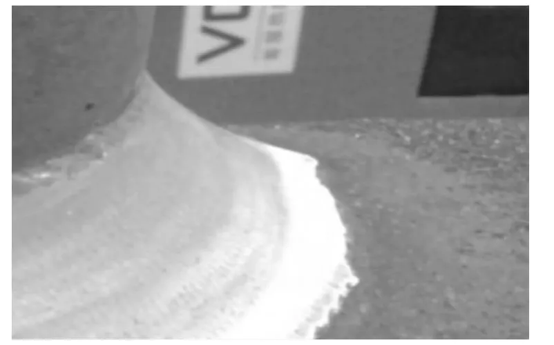
Fig.8 Using the adaptive control grinding
Through the automation design of pipe weld grinding and pressure control of adaptive processing.It achieves the design requirements,has reached the requirements of surface quality and dimension.Addition it,it can reduce production costs,the risk of health and safety,the processing time,realize automated production.It satisfies the modern pursuit of goals of high efficiency and reliability,at the same time,it meets the development direction of intelligent manufacturing and green manufacturing of mechanical engineering technology.
[1] ZHANG Mingde,GUO Xiaodong,HUANG Yun,et al.The calculation of cutter location data and precision controlling for CNC abrasive belt grinding turbine blade profiles based on ACIS[J].Machine Tool&Hydraulics,2008(36):33-35.
[2] HAN Qingyao,MAO Xinhua.Study on orientation processing of large-scale and intricate surface based on selfadaptive processing technology[J].Machine Tool&Hydraulics,2007,35(5):60-61.
[3] Khellouki A.The effect of abrasive grain’s wear and contact conditions on surface texture in belt finishing[J].Wear,2007(9):81-87.
[4] ZHANG X,Kuhlenkoetter B,Kneupner K.An efficient method for solving the signorini problem in the simulation of free-form surfaces produced by belt grinding[J].International Journal of Machine Tools& Manufacture,2005,45:641-648.
[5] Axinte D A.Investigations on belt polishing of heat-resistant titanium alloys[J].Journal of Materials Processing Technology,2005,166:398-404.
[6] SUN Yunquan.Accurate robotic belt grinding of workpieces with complex geometries using relative calibration techniques[J].Robotics and Computer-Integrated Manufacturing,2009,25:204-210.
管座焊缝自适应砂带磨削控制方法
张明德*,王兴龙
重庆理工大学机械工程学院,重庆 400054
针对管座焊缝的自动化磨削问题,建立了焊缝几何模型,提出了刀位计算与加工质量控制方法,采用了自适应焊缝磨削加工过程控制方法,并进行了加工实验。实验结果表明:该方法可有效解决磨削过程中出现过切、欠切等问题,从而解决了管座焊缝磨削质量的控制难题。
曲面;建模;压力;自适应加工
TH165
10.3969/j.issn.1001-3881.2013.24.012
2013-06-25
