Fracture Assessment for Electron Beam Welded Damage Tolerant Ti-6Al-4V Alloy by the FITNET Procedure
2013-01-20LUWeiSHIYaowuLIXiaoyanandLEIYongping
LU Wei*,SHI Yaowu,LI Xiaoyan,and LEI Yongping
College of Materials Science and Engineering,Beijing University of Technology,Beijing 100124,China
1 Introduction
Thick Ti-6Al-4V titanium alloy has been widely employed in the load-bearing structures of aircraft,submarine shell for deep underwater detection,and gas bottles of satellite launch vehicles due to the superior combination properties,such as high specific strength,low specific gravity,and high corrosive resistance[1-2].Driven by the increasing damage tolerant requirements for the significant structures,damage tolerant Ti-6Al-4V(TC4-DT)alloy is developed on the basis of conventional Ti-6Al-4V alloy by decreasing the interstitial element content.The alloy exhibits well damage tolerant in terms of high strength,fracture toughness and fatigue resistance against crack growth,thus the titanium alloy with high thickness begins to apply in some significant structures[3-4].
Welding technique is widely used to manufacture titanium alloy structures in modern industry.Reliable shielding of weld zone is essential during the welding considering the fact that titanium is easily reactive towards atmospheric gas at the temperature above 350 ℃[5].Electron beam welding(EBW) is considered as the most suitable welding method to join thick titanium alloy due to its advantages,such as high power density,low heat input,and high vacuum environment[6].These advantages are helpful to achieve large penetration,low distortion,light weight and better quality of welded joint.
Welded joint usually exhibits microstructure and mechanical heterogeneity due to the different thermal cycle experienced during welding.The heterogeneity may give an influence on the mechanical properties and deformation performance of the structures.Moreover,welding residual stresses and weld defects easily exist in the welds.The weld defects usually become the crack nucleation due to the stress concentration,and then the crack instability extension and failure occurs under larger loading or the inadequate fracture toughness.Therefore,integrity assessment of welded structures is crucial for investors,designers,and supervising production and exploitation engineers[7].
Several defect assessment methods specific to the strength mismatching welded structures are proposed up to now,such as ETM-MM[8],R6[9]and SINTAP[10].The fitness-for-service(FFS) FITNET procedure completed in 2006 is widely accepted as a unified assessment procedure to combine the strengths of the methods available[11].This procedure contains four major analysis modules including fracture,fatigue,creep and corrosion.The fracture module is mainly based on the SINTAP and R6 procedure,which is suitable for the assessment of metallic structures and component with welds when the failure mechanism considered is fracture.The use of fracture module of the FITNET procedure is important specifically to assess the structural significance of welding induced defects(pores,flaws or cracks),particularly crack-like flaws that need to be assessed to prevent failure of the welded component during service.
Till now,a number of studies have been carried out to validate the application of the FITNET FFS procedure for the various steels and some aluminum alloy welded structures with various configurations[12-15].It is found that the fracture module of the FITNET FFS procedure provides an accuracy estimate of critical load or crack size below which failure will not occur.However,few validation studies have been reported for titanium alloy and its welded structures,especially the welded structures by advanced welding techniques.Considering the specific features of titanium alloy and the EB welded joints(narrow weld width,strength mismatch,etc),some basic equations of FITNET FFS procedure may be not suitable for the fracture assessment of titanium alloy and its EB welded joints.Thus,there is an increasing need of fitness-for-service fracture assessment for the EB welded titanium structures using FITNET FFS procedure with the increasing application of the material and technology in important load-bearing structures.In previous studies,the analysis of the mechanical properties including tensile properties and fracture toughness of EB welded thick TC4-DT joints have been made to achieve basic input data of fracture assessment[16].The aim of the present work mostly focus attention on the fracture assessment of these joints,and to provide a validation for the application of the FITNET FFS procedure to the EB welded thick titanium alloy.
2 Fracture Module of the FITNET FFS Procedure
The fracture module of FITNET FFS procedure[11]is based on the principle that failure is deemed to occur when the crack driving force exceeds the material's ability to resist the extension of the crack (fracture toughness of material).Two approaches can be adopted to assess the integrity of cracked structures in the FITNET FFS procedure:the failure assessment diagram(FAD) approach and the crack driving force(CDF) approach.The two approaches provide identical results as long as the same input data are used.In this paper,the FAD approach is used.
In the FAD route,a failure assessment line(FAL) is constructed in terms of two parameters,KrandLrby
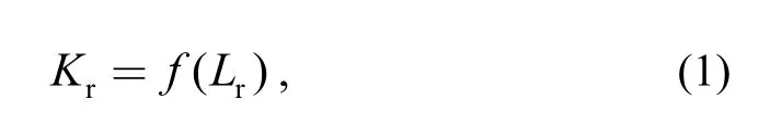
whereKris the crack driving force in terms of stress intensity factorKInormalized by the materials fracture toughnessKmat,andLris the ratio of the total applied loadFgiving rise to the primary stresses to plastic limit loadFY.
It is necessary to plot an assessment point or a set of assessment points of coordinates(Lr,Kr) calculated under the loading conditions applicable to use the FAD approach.The assessment of the component is then based on the relative location of the failure assessment point and the FAL,as shown in Fig.1.The assessment points lying on or within the envelope indicates that the structure is acceptable against this critical condition.The point lying outside the envelope indicates that the structure had failed to meet this critical condition.
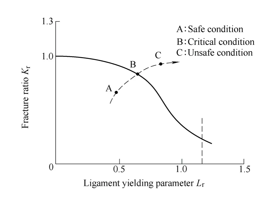
Fig.1.Failure assessment diagram for fracture initiation
Different analysis options have been provided to plot the FAL in the FITNET FFS Fracture Module depended on the quality and detail of the material's property data available.There are one basic option,three standardized options and two advanced options.The higher the option of analysis,the higher is the quality required of the input data,and the more complex are the analysis routines.Standard option 1 requires values of the material's yield and tensile strength.The option analysis is developed for homogeneous components or the weldments with the mismatch ratioM(the yield strength of weld metal normalized by that of base metal) less than 10%.Standard option 2 is the mismatch option,which is the extension of option 1 to weldments by incorporating the strength mismatch effect when the mismatch ratio is more than 10%.The method requires yield strength and tensile strength of both the base and weld metal.Standard option 3 requires full stress strain data and can be applied either to homogeneous component or to the mismatch component.Advanced option 4 requires results of elastic-plastic finite element(FE) analysis of the defective component,while option 5 invokes constraint treatment and also requires results of detailed elastic-plastic analysis of flawed component.
In this paper,only some options of FITNET FFS procedure will be used.The required information for the fracture assessment is schematically illustrated in Fig.2.
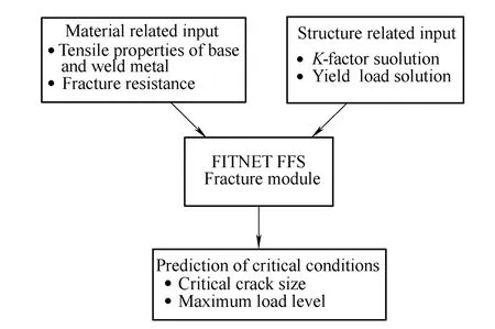
Fig.2.Required input information of the FITNET FFS procedure
3 Experimental Procedure and Material Properties
3.1 Materials and electron beam welding process
The materials used in this study were 50 mm thick TC4-DT plates in duplex annealing condition.Nominal compositions (wt.%) of the alloy were 5.6-6.35 Al,3.6-4.4 V,≤0.25 Fe,≤0.05 C,≤0.03 N,≤0.0125 H,≤0.13 O and balance Ti.EB welds (butt-joints) were produced along the transverse direction of the plate in vacuum chamber of a high voltage ZD 150-15A EBW machine using the heat input of 24.75 kJ/m,focus current of 2191 mA and velocity of 800 mm/s.
3.2 Tensile properties
As mentioned in the previous section,it is found that tensile properties of base metal and weld metal are the important input parameters for the fracture assessment of weldments.In this work,micro tensile specimens were used to determine the tensile properties of base and weld metal.As the welded joints are thick,the tensile properties of weld metal along different weld depth were measured.Fig.3 shows the sampling position and tensile specimen dimension defined based on the small size geometry of the ASTM E8M-04 specification[18].Tensile tests were performed at room temperature using a MTS testing system with a displacement extensometer attached in the gage length of 15 mm,and the full stress strain data were recorded.
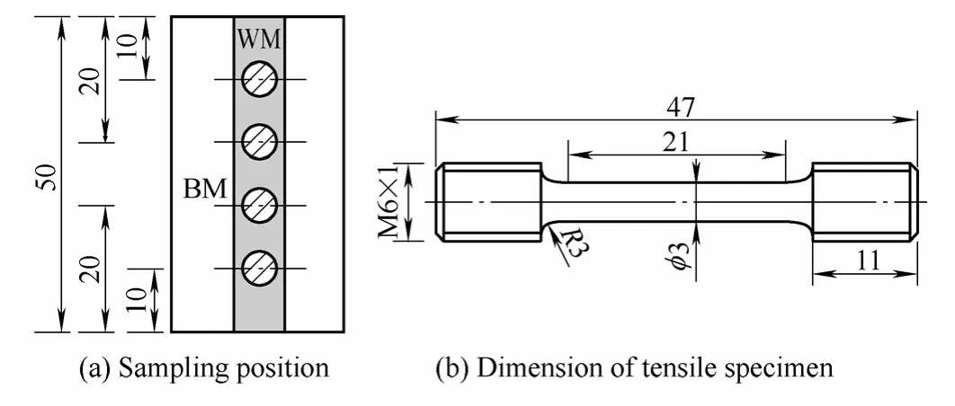
Fig.3.Schematic illustration of specimen
The stress strain curve of both the base and weld metal is continuous and do not exhibit a yield plateau,as shown in Fig.4.The tensile test results are given in Table 1.
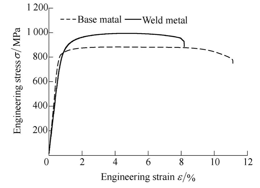
Fig.4.Engineering stress strain curves
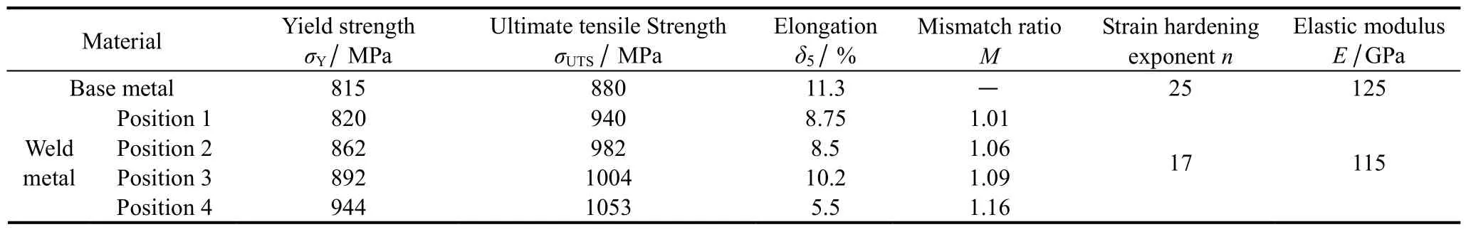
Table 1 Tensile properties of base metal and weld metal
It is found that the yield strength of weld metal is larger than that of base metal,which means that the EB welded joints are weld strength overmatching.The reason for this is the formation of acicular martensite in the fusion zone after the EBW in comparison with primary α and lamellar(α+β) bimodal structure of base metal(Fig.5).Moreover,the weld strength mismatch ratios along different weld depth are different.The mismatch ratio increases with the weld depth increasing.At the position from 1 to 3,theMis smaller than 10%,while at position 4,theMincreases to 1.16.In the previous section,it is known that when the strength mismatch ratio is smaller than 10 %,the options for homogeneous materials should be used to assess the welded joint.For the present thick-walled welds,both the conditions ofM>10% andM<10% are found.Therefore,in the present work,the weld metal is still supposed as homogeneous material,and both the homogeneous options and mismatch options were used for the fracture assessment.The maximum strength mismatch ratio of 1.16 was used for the case of mismatch options.
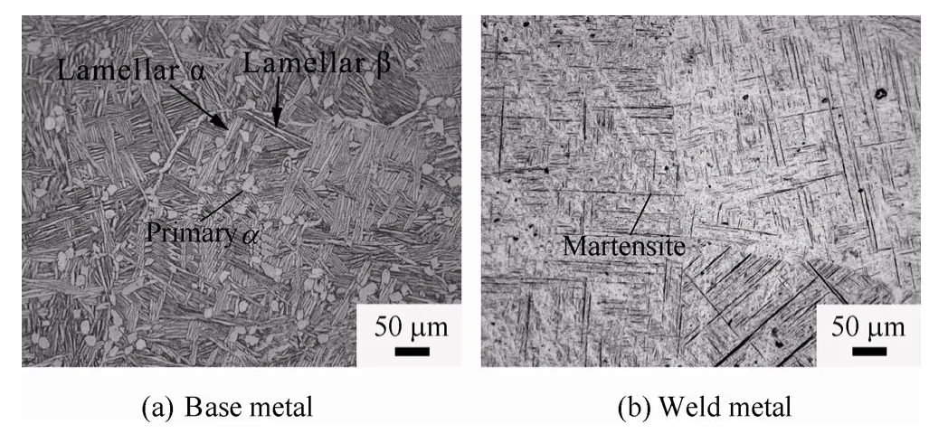
Fig.5.Microstructure of EB welded TC4-DT joints
3.3 Fracture properties
Fracture toughnessKICof the base metal and EB welded joints was tested using CT specimen based on ASTM E399-09 standard[16].The specimen depth is the depth of primary plates.The geometry and dimension of CT specimens are shown in Fig.6.Starter notch and fatigue precracking were carried out to develop an initial sharp crack.The notch was spark machined at the center of the weld metal for the welds and in the L-T direction for the base metal.The final crack length over specimen width a/W was 0.5.The fracture toughness tests were performed using a MTS testing system at room temperature.
Fig.6.Schematic illustration of CT specimen
Both the base metal and welded joints exhibit ductile dimpled fracture features (Fig.7).The fracture toughness values is shown in Table 2.The toughness of base metal is higher than that of weld metal.The toughness reduction of the weld metal is mainly related to the needle martensite formed in the weld metal.
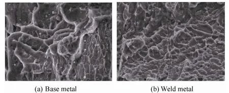
Fig.7.Fractography of CT specimens

Table 2 Fracture properties of base metal and weld metal
The FITNET FFS procedure indicates that the characteristic value of the fracture toughnessKmatmay be based on the minimum value obtained in a set of three tests.In this work,the failure mechanism of base metal and welded joints is ductile,thus,Kmatmay be based on the minimum value.According to the Table 2,Kmatis chosen to be 104 MPa·m-1/2for the base metal,and 70.1 Mpa·m-1/2for the welded joints.
4 Fracture assessment for EB welded thick-walled TC4-DT alloy
FALs of standard options are mainly based on some engineering equations.The application of these equations has been validated in many researches for the various steels and some aluminum alloy welded structures.However,there is a need for the validation of these equations for titanium alloy and its welded structure.As the FAL of option 4 is proposed based on the detailed elastic-plastic FE analysis,it was used to validate the suitability of FAL equations of standard options.Moreover,the standard options were used to predict the maximum load level of CT specimen,and the application of these options was validated by experiment results.
4.1 Standard options for homogeneous component
Option 1 and option 3 can be used for homogeneous component,which are decribed as follows:
Option 1
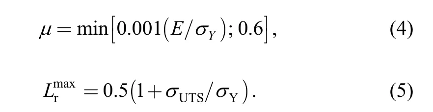
The FAL is computed by using
whereNis strain hardening coefficient,
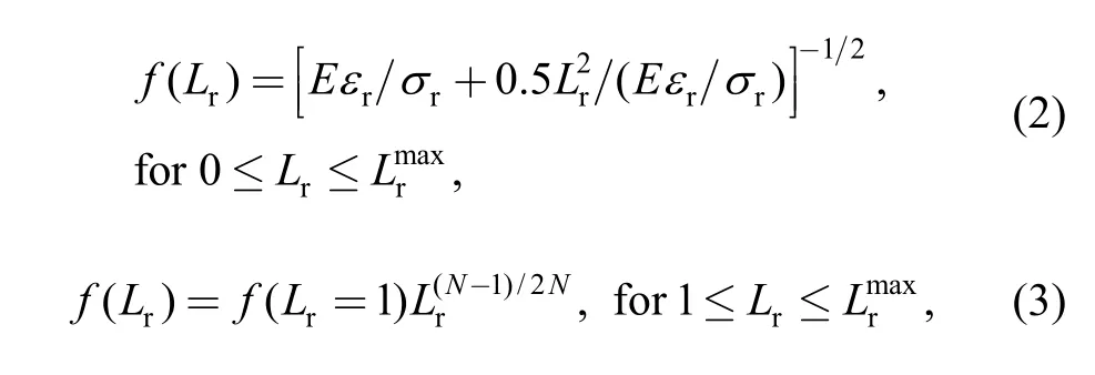
Option 3
The FAL for homogeneous component is given by
whereεris the true strain obtained from the uniaxial stress-strain curve at a true stressσrofLrσY.
4.2 Standard options for mismatch component
Option 2 and option 3 can be used for mismatch component,which are decribed as follows:
Option 2
The FAL of option 2 is given as follows:
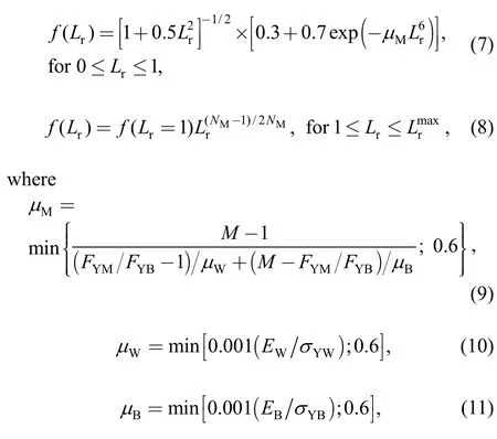
and the plastic collapse limitmaxrL(SINTAP procedure):
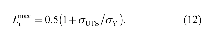
In the FITNET procedure,Eq.(12) is replaced by
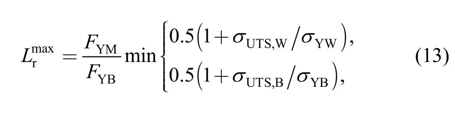
whereFYMandFYBare the yield load for the mismatch and base material component,respectively.
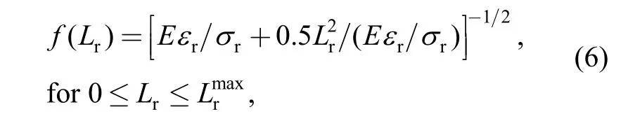
Option 3
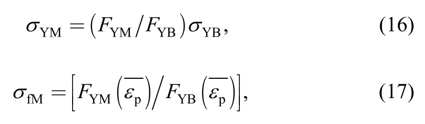
The FAL for mismatch component is given by
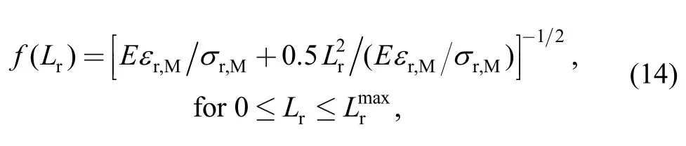
whereεr,Mis the equivalent true strain obtained from the uniaxial stress strain curve at a equivalent true stressσrofLrσY.
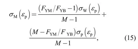
The equivalent stress-strain curve of mismatch material is defined as follows:whereFYM/FYBis defined forM(εp)=σW(εp)/σB(εp) as a function of the plastic strainεpof the plastic branch of the stress strain curve.
The equivalent true stress-strain curves for the mismatch components are dependent on the properties of both the base and weld metal,as well as the geometry of the component.The curve for the present joints with a center crack in tension(CCT) is shown in Fig.8.The stress-strain curve of weld metal in weld position 4 is used to construct the curveasMat the position is more than 10% .
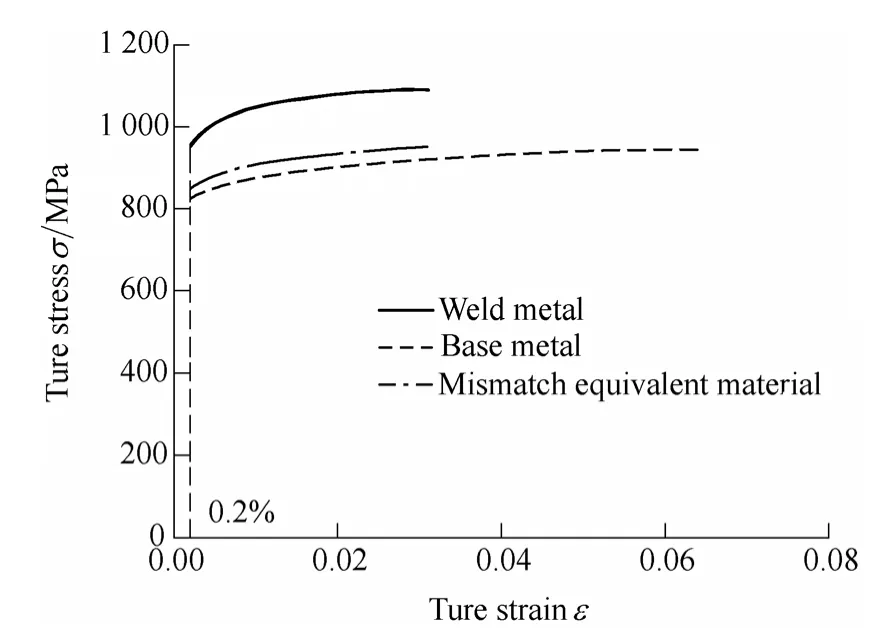
Fig.8.True stress-strain curve for equivalent material
4.3 Finite element validation of standard options
Option 4 was used to validate the applicability of standard options FALs in this section.
Option 4
When the elastic-plastic J-integral for the mismatch component of interest is available,the FAL can be determined from
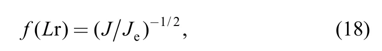
whereJeandJare the values of the J-integral from the elastic and elastic-plastic analyses,respectively.
4.3.1 Finite element analysis
J-integral may be available from a FE analysis.In the FE analysis,the actual weld configurations were simplified to be composed of only base metal and weld metal.The heat affected zone was included in the weld metal due to its similar microhardness with the weld metal[16].Moreover,the tensile mode is dominant in the loading of most structures,and wide plate test is widely accepted to be a more realistic method to assess the fracture behavior of the welded structure.Therefore,in the present work,the 2D CCT specimen withW=50 mm,2H=8 mm,a/W=0.5 is considered,as shown in Fig.9(a).
Both elastic and elastic-plastic analyses were carried out to obtainJandJe,respectively,using a commercial software ABAQUS.The required material properties are indicated in Table 1,including the strain hardening exponent and elastic modulus.A quarter of the specimen was analyzed due to the symmetry,and the crack tip singularity was designed using collapsed element.The finite element mesh is shown in Fig.9(b).The model includes 384 elements and 1 247 nodes.Moreover,reduced integration eight-node plain strain elements (CPE8R) were used considering the high thickness of the specimen.The value ofJandJecan be extracted directly from ABAQUS.
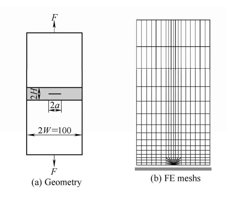
Fig.9.Schematic illustration of CCT specimen
4.3.2 Component-related input parameters
The component-related input parameter for the FALs determination of FITNET FFS procedure is the mismatch yield loadFYM,the solutions of which has been provided in the Annex B of FITNET FFS procedure[11].The details are not given for the sake of space.
4.3.3 Comparison of options
Fig.10 compares the FAL of option 4 with those of standard options.The comparison for the case of homogeneous material is shown in Fig.10(a),whereas the comparison for the case of mismatch material is shown in Fig.10(b).It is found that the FALs are in the correct order for the two cases.The higher option curve is associated with less conservation,while the lower option curve is associated with more conservation.
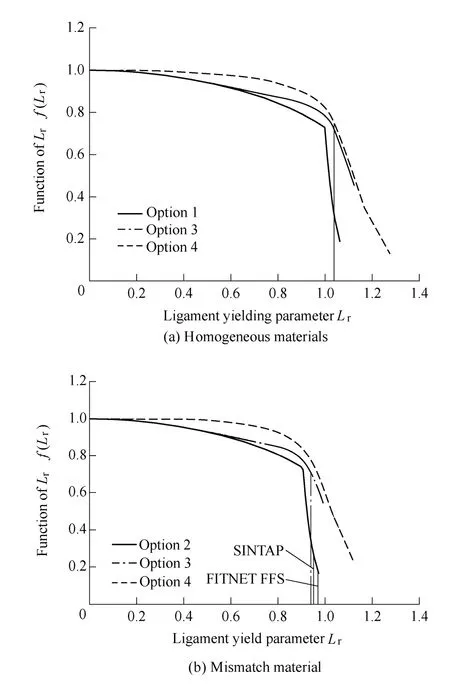
Fig.10.Comparison of FALs from various options
For the homogeneous options,the FAL of option 1 is quite close to that of option 3,and the FALs of option 1 and option 3 are slightly conservatism comparing with that of option 4.This may be dependent on the inherent properties of TC4-DT alloy and its EB welds.From Table 1 and Fig.5,it is found that the plastic branch of stress-strain curve is quite flat,and the strain hardening properties beyond yield is weak.This will make the cut-off of plastic collapsebe quite close to 1.Moreover,the benefit of a higher option is not obvious at the values ofLr≤ 0.8[11].Therefore,the FALs of option 1 and option 3 show excellent agreement.Due to the flat stress strain curve beyond yield,the assessment of option 1 and option 3 exhibit conservatism,which is similar with the results for the case where the material shows a yield plateau[20].
For the mismatch options,the similar trends are found with that of homogeneous options.The FAL of option 2 is quite close to that of option 3,and the FALs of option 2 and 3 are slightly conservatism.However,it is noted that theof option 3 is smaller than that of option 2,which may be questionable.It is known that the option 3 for mismatch component is based on the equivalent stress strain curve,which is derived from the full stress-strain curves of both base and weld metal.The equivalent curve is strongly affected by the true plastic strain of base and weld metal.In the present work,very obvious difference of true plastic strain exists between the weld metal and base metal (Fig.8).The equivalent stress strain curve is restricted by the weld metal,and then gives an influence on the value ofin option 3.Therefore,the application of option 3 to the defective assessment of mismatch component with plastic collapse dominated failure should be treated with caution,when there is obvious difference of plastic deformation between the base metal and weld metal.In addition,thedefinition of SINTAP procedure is more close to the option 3 than that of FITNET FFS procedure,so the SINTAP procedure equation ofis suggested for the present materials.
The effect of strength mismatch on the FALs of standard options is also investigated and shown in Fig.11.It is found that the effect of mismatch may be negligible due to the narrow weld width of EB welds.
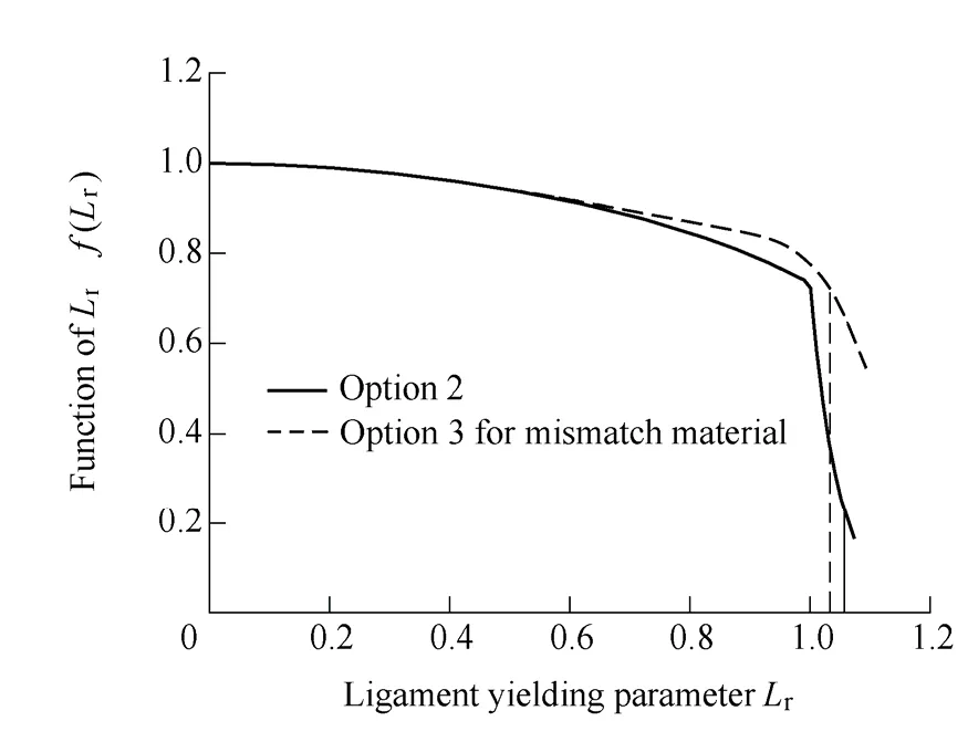
Fig.11.Effect of strength mismatch on the FALs
4.4 Expermental validation of standard options
In this section,the CT specimen of the fracture toughness testing was used to validate the applicability of standard options of FITNET FFS procedure for the present EB welds by comparing the predicted maximum load level with the experimental results.
4.4.1 Component-related input data and calculation of Kr
The component-related input parameter for the prediction of critical load using FITNET FFS procedure is the mismatch yield loadFYM,and the stress intensity factorKI.The solutions ofFYMhave been provided in Ref.[21].The details are not given for the sake of space.
The stress intensity factorKIfor CT specimen is given in a closed form solution as
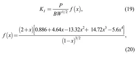
wherex=a/W,Fis the applied load,Wis the width of the specimen,ais the crack length andBis the specimen thickness.SinceK-factor is a geometrical function,it is also valid for welded specimen.
Krcan be evaluated from primary and secondary stresses.The secondary stress for weldments is usually the residual stress due to the welding process.In this paper,the post weld heat treatment was performed to reduce the as-welded residual stresses.Therefore,the effect of secondary stresses is ignored during the fracture assessment,and only primary stress was used to calculate theKr.
4.4.2 Prediction of maximum loads
The crack initiation analysis of standard options was carried out to predict the maximum loads of CT specimen(Fig.12),which was then compared with the measured maximum loads in the experiment,as shown in Fig.13.
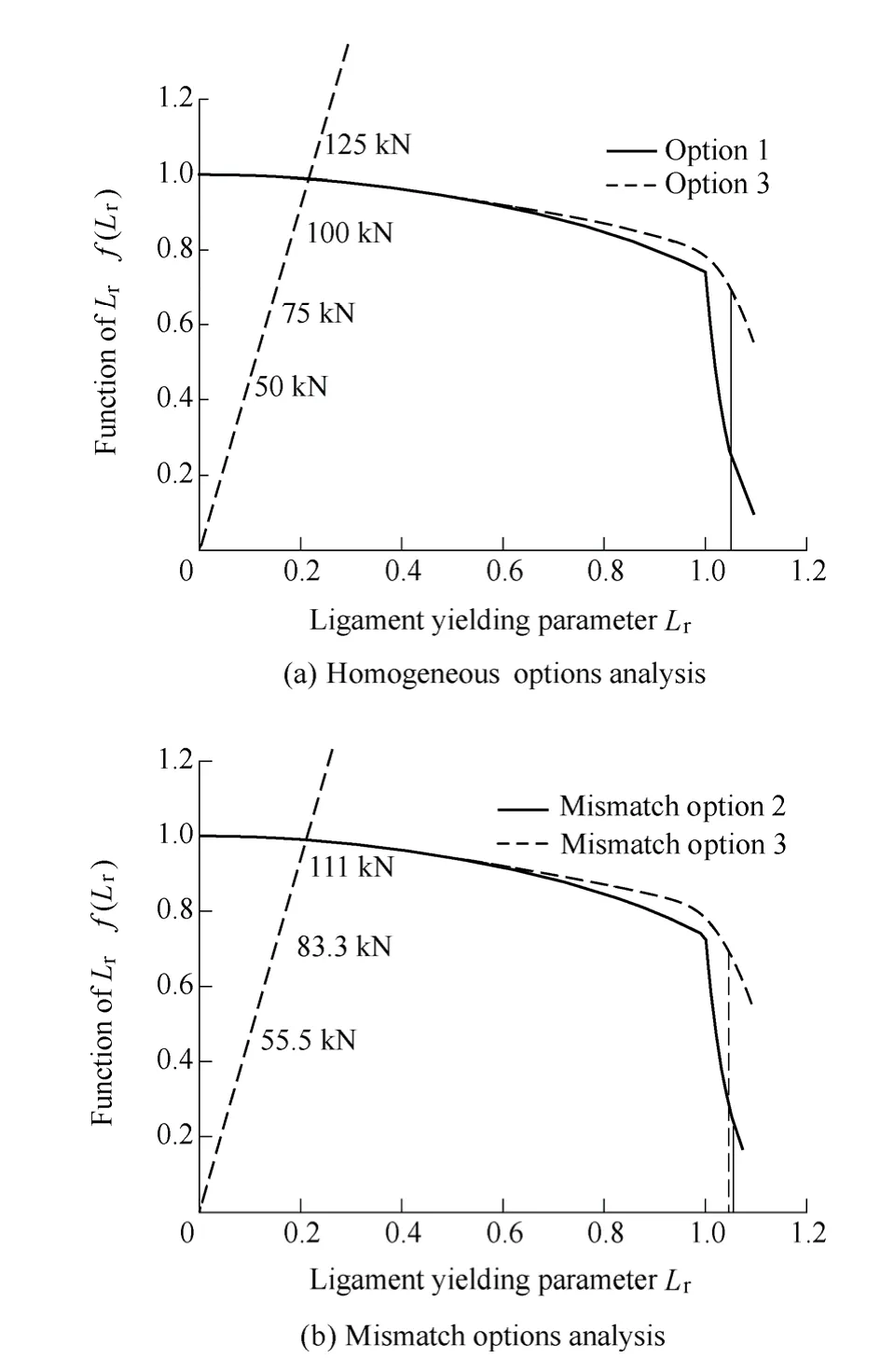
Fig.12.Prediction of the maximum load of CT specimens
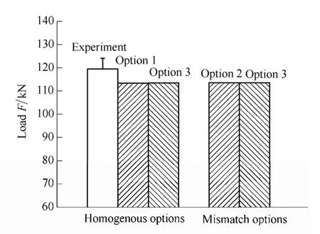
Fig.13.Comparison of predicted maximum load by standard options with experimental result
It is found that for both the case of homogeneous and mismatch option,the predicted maximum loads of lower standard options(option 1 and option 2) are almost the same with that of option 3,which are all quite close to the experimental results.This means that the FITNET FFS procedure is applicable to the fracture assessment of thick-walled EB welded TC4-DT titanium alloy.In addition,the predicted maximum loads using mismatch options are similar with those using homogeneous options.The homogeneous options do not exhibit more conservative.All of this demonstrates that the potential advantage of applying higher options or mismatch options is not obvious for the fracture assessment of the thick-walled titanium alloy welds.Standard option 1 can be used to achieve accurate enough results.The experimental validation provides confidence of the utilization of the FITNET procedure to assess titanium alloy and its EB welds.
The results of the present validation work clearly shows that the suitability of the FITNET procedure for the thick-walled titanium alloy with narrow EB welds,when failure is fracture-dominated.Further studies are desirable for the fracture assessment of thin-walled titanium alloy and its welds covering plastic collapse-dominated failure.
5 Conclusions
(1) The FALs of standard options of FITNET procedure is suitable for the TC4-DT alloy and its EB welded joints.Nevertheless,the applicability of option 3 to mismatch material should be treated with caution for the plastic collapse analysis.
(2) Accurate estimation of the maximum loads can be achieved using both option 1 and option 3 for homogeneous material,and option 2 and option 3 for mismatch material.
(3) For fracture assessment of the present EB welded TC4-DT joints,there are no potential advantages of applying higher options or mismatch options.The welds can be treated as homogeneous material,and standard option 1 can be used to achieve accurate enough results.
[1]LU Wei,SHI Yaowu,LEI Yongping,et al.Effect of electron beam welding on the microstructures and mechanical properties of thick TC4-DT alloy[J].Material and Design,2012,34:509-515.
[2]DENG Jianxin,LI Yousheng,ZHANG Hui.Adhesion wear on tool rake and flank faces in dry cutting of Ti-6Al-4V[J].Chinese Journal of Mechanical Engineering,2011,24(6):1 089-1 094.
[3]SARESH N,PILLAI M G,MATHEW J.Investigation in to the effects of electron beam welding on thick Ti-6Al-4V titanium alloy[J].Journal of Material Processing Technology,2007,192-193:83-88.
[4]ZHU Zhishou,MA Shaojun,WANG Xinnan,et al.Study on fatigue crack propagation rate of TC4-DT damage tolerant titanium alloy[J].Titanium Industry Progress,2005,22:10-13.(in Chinese)
[5]ZHANG Zhu.Metallurgy and heat treatment of Ti alloy[M].Beijing:Metallurgical Industry Press,2009.(in Chinese)
[6]BARREDA J L,SANTAMARIA F,AZPIROZ X,et al.Electron beam welded high thickness Ti6Al4V plates using filler metal of similar and different composition to the base plate[J].Vacuum,2001,62:143-150.
[7]LU Wei,SHI Yaowu,LI Xiaoyan,et al.Limit load solution for electron beam welded joints with single edge weld center crack in tension[J].Chinese Journal of Mechanical Engineering,2012,25(3):624-628.
[8]SCHWALBE K H,KIM Y J,HAO S,et al.EFAM ETM-MM 96:The ETM method for assessing the significance of crack-like defects in joints with mechanical heterogeneity(strength mis-match)[S].Germany:GKSS Research Centre,1996.
[9]Appendix 16 in R/H/R6-Revision 3:Allowance of strength mis-match e.ect[S].British Energy,1997.
[10]Final procedure:structural integrity assessment procedures for European industry[S].Germany:GKSS Research Centre,1999.
[11]FINNET fitness for service(FFS) procedure-final draft[S].Germany:GKSS Research Centre,2006.
[12]YENI C,KOςAK M.Fracture analysis of laser beam welded superalloys Inconel 718 and 625 using the FITNET procedure[J].International Journal of Pressure Vessels and Piping,2008,85:532-539.
[13]IHOR D,ANDRZEJ N.Application of the standard options of the FITNET procedure to the structural integrity assessment of welded specimens containing cracks[J].International Journal of Pressure Vessels and Piping,2007,84:475-486.
[14]CICERO S,YENI ς,KOςAK M.Fracture analysis of strength undermatched Al-Alloy welds in edge cracked tensile panels using FITNET procedure[J].Fatigue &Fracture of Engineering Materials,2008,31:738-753.
[15]TAKUYA O,MASAO I,TOSHIYUKI S.Fracture assessment for a dissimilar metal weld of low alloy steel and Ni-base alloy[J].International Journal of Pressure Vessels and Piping,2012,90-91:61-68.
[16]LU Wei,LEI Yongping,LI Xiaoyan,et al.Effect of electron beam welding on fracture behavior of thick TC4-DT alloy[J].Science and Technology Welding and Joining,2012,17,277-281.
[17]ASTM E8M-04:Standard test method for tensile testing of metallic materials[S].ASTM,2009.
[18]ASTM E399-09:Standard test method for linear-elastic planestrain fracture toughness KIC of metallic materials[S].ASTM,2009.
[19]LU Wei,LI Xiaoyan,LEI Yongping,et al.Study on the mechanical heterogeneity of electron beam welded thick TC4-DT joints[J].Materials Science and Engineering A,2012,540:135-141.
[20]KIM Y J,KOςAK M,AINSWORTH R A,et al.SINTAP defect assessment procedure for strength mismatched structures[J].Engineering Fracture Mechanics,2000,67:529-546.
[21]KIM Y J,SCHWALBE K H.Compendium of yield load solutions for strength mismatched DE(T),SE(B),and C(T) specimens[J].Engineering Fracture Mechanics,2001,68:1 137-1 151.
Biographical notes
LU Wei,born in 1988,is currently a PhD candidate atCollege of Materials Science and Engineering,Beijing University of Technology,China,in 2010.Her research interests include electron beam welding and integrity assessment of structures.
Tel:+86-10-67 392523;E-mail:luwei87@emails.bjut.edu.cn
SHI Yaowu,born in 1941,is currently a professor atCollege of Materials Science and Engineering,Beijing University of Technology,China.He received his PhD degree fromAston University,United Kingdom,in 1982.His research interestsinclude numerical simulation and integrity assessment of weld structure.
Tel:+86-10-67 392523;E-mail:shiyw@bjut.edu.cn
LI Xiaoyan,born in 1963,is currently a professor atCollege of Materials Science and Engineering,Beijing University of Technology,China.He received his PhD degree fromHarbin Institute of Technology,China,in 1992.His research interests include welding mechanics,welding structures and NDT,etc.
Tel:+86-10-67 391856;E-mail:xyli@bjut.edu.cn
LEI Yongping,born in 1957,is currently a professor atCollege of Materials Science and Engineering,Beijing University of Technology,China.He received his PhD degree fromXi'an Jiaotong University,China,in 1994.His research interests include numerical simulation and assessment of auto parts.
Tel:+86-10-67 391759;E-mail:yplei@bjut.edu.cn