Design and Optimization for the Occupant Restraint System of Vehicle Based on a Single Freedom Model
2013-01-20ZHANGJunyuanMAYueCHENChaoandZHANGYan
ZHANG Junyuan,MA Yue*,CHEN Chao,and ZHANG Yan
State Key Laboratory of Automobile Simulation and Control,Jilin University,Changchun 130025,China
1 Introduction
Nowadays,CAE and physical sled tests are the most widely used methods in vehicle safety developments[1–2].Therefore,the advanced CAE method,for example,conducting the simulation model,DOE test method and optimization,have got considerable progress[3–6].However throughout the vehicle crash event,the interactions between vehicle,occupant,restraint system (VOR) are complicated and the ways to dissipate the occupant’s total kinetic energy are varied.If the design of a vehicle occupant restraint system has an over-reliance on CAE tools,some design errors and imperfections are difficult to correct at that time,and a large amount of time will be needed[7].This is because the CAE methods can only be done with detailed 3D models or physical samples.In addition,the good theoretical guidance and the initial values are often deficient in the development of occupant restraint systems,which are required not only for the long-term accumulation of the test statistics and design experience,but also the in-depth understanding of the kinematics and dynamic relationships between the vehicle,occupant,and restraint system.
The occupant energy dissipation mechanism in the vehicle frontal crash process was studied and the restraint energy and the ridedown energy were analyzed by EVANS,et al[8]and BONELLO[9],in 1992.The single freedom vehicle-occupant model was built,and then it was used to calculate the restraint energy and the ridedown energy from the view of mechanism kinematics by HUANG,et al[10]in 1995.The relationships between the vehicle frontal crash pulse and the occupant response were studied in detail in Ref.[11]in 2002.On the domestic side,the effect of various crash pulses on occupant chest acceleration is studied by ZHANG,et al[12],based on the law of conservation of energy in 2008.However,these public references mainly present the theory in the vehicle collision event,and cannot be used to directly guide the forward design of the vehicle in practical application.
A concept design approach based on the single freedom vehicle-occupant model is proposed in this paper.The design principle of the restraint stiffness is presented by studying the relationships between the ridedown efficiency,the restraint stiffness,and the occupant response.An optimization design of a passenger vehicle restraint system is solved by the concept design and its final result is validated by MADYMO which is the most used software in restraint system design simulation and sled tests.
2 Analysis of Occupant Energy in Vehicle Crash Progress
At the very beginning of the vehicle crash,the vehicle and occupants have the same initial velocity to the absolute coordinate (Fig.1).During the crash event,there will be relative displacement between the occupant and the vehicle.The restraint forces acting on the occupant are produced by this relative displacement.The occupant dynamic equation is
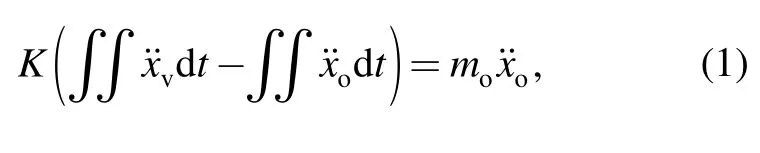
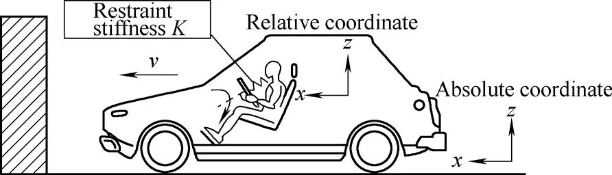
Fig.1.Absolute and the moving coordinate systems in vehicle crash
If the restraint stiffness is too low,the relative displacement between the occupant and the vehicle will be large,which would cause the occupant to impact the vehicle interior.To the contrary,the restraint force acting on the occupant will be high.Both of them will probably bring serious injury to the occupant.
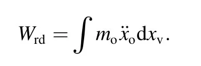
It has been found that,some of the occupant’s energy,transforming through the restraint system to the vehicle,would be absorbed by crushing the front structure,and the other portion of the occupant’s energy is absorbed by deforming the components of the restraint system.The first part of this energy,called ridedown energy,is defined as
The second part of energy,called restraint energy,is defined as
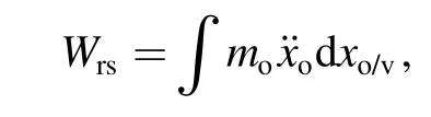
wherexvis the vehicle displacement,xo/vis the relative displacement.The restraint energy is mainly absorbed by the deformation of safety airbags,safety belts and other components such as the seat and steering system.The total occupant energy is
and the ridedown efficiency is defined as
This two parts of energy influence the occupant injury directly and the mode of distribution can be changed by optimizing the vehicle structure and the restraint system in order to reduce the occupant injury level[13–16].
3 Discussion of the Restraint Stiffness Based on the Single Occupant-vehicle Model
3.1 Energy distribution in vehicle crash process
One A-class car is taken as an example in this paper.The vehicle acceleration (impact pulse) and occupant acceleration data in 50 km/h frontal rigid barrier (FRB)vehicle crash tests are shown in Fig.2 and Fig.3.
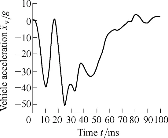
Fig.2.Vehicle acceleration
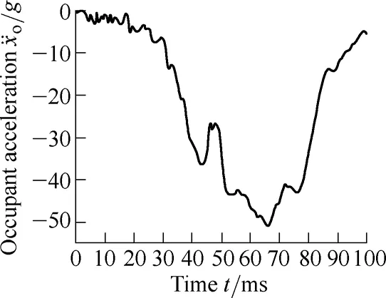
Fig.3.Occupant acceleration
The restraint curve is defined as the occupant acceleration with respect to relative displacement and the ridedown curve is defined as the occupant acceleration with respect to the vehicle displacement,as shown in Fig.4.The dynamic crash zone of the car is 0.425 m,and the maximum relative displacement between occupant and vehicle is 0.22 mm.The calculated driver restraint energy is 68.0 J/kg and the ridedown energy is 30.4 J/kg in this crash test.Note that the restraint energy curve,ridedown energy curve and other results are all calculated by MATLAB in this paper.
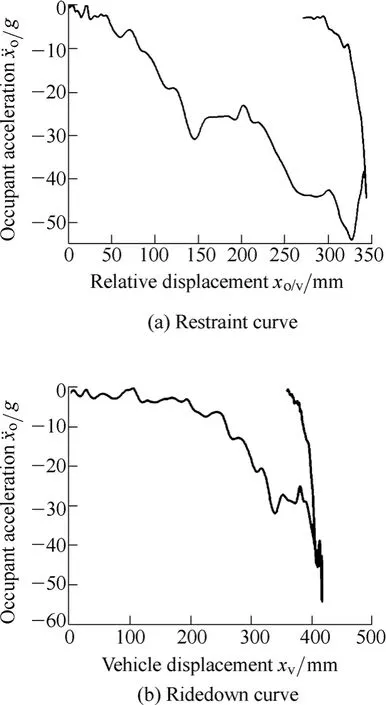
Fig.4.Acceleration vs.displacement
3.2 Simplified restraint system mechanical model
A single-degree-of-freedom occupant-vehicle model,including the spring and mass,was built,which is used to understand the mechanic relationships between the restraint stiffness and the occupant response,as shown in Fig.5.The vehicle and the occupant are both simplified to mass points,and the restraint system is simplified to a spring with the stiffness (kis spring stiffness,δis restraint slack andvois initial impact velocity).This SDOF reflects the interplay between the vehicle and the occupant.
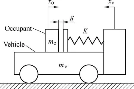
Fig.5.Single freedom occupant-vehicle model
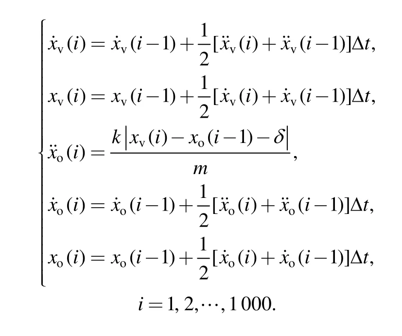
An iterative calculation equation is established to solve the single freedom model by a MATLAB program.The main calculation equations are shown below from equation as follows.Note that the initial displacements of vehicle and occupant are zero,and the initial velocities are 50 km/h.The input to this equation is the vehicle acceleration,and the load limiter levelL.The vehicle displacementxvcan be solved by integration,and then the restraint forceFbased on the relative displacement |xv-xo| can be solved,and the occupant accelerationcould be obtained.
The dynamic equation of the SMF can be represented as
By comparing the responses with that of a physical test and the solution from a MADYMO model (Fig.6 and Fig.7),the effectiveness of the SDOF program could be validated.
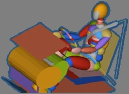
Fig.6.MADYMO simulation model
Fig.7.Sled test
3.3 Relationship between restraint system stiffness and ridedown efficiency
There are three kinds of curve shapes (line 1 to 3),including a straight curve,convex curve and concave curve,representing the most common shapes of restraint stiffness(Fig.8).By the calculation of the SDOF,the ridedown efficiencies are 30%,40%,and 13%,respectively.These results indicate the fact that the restraint stiffness with the convex shape can lead to higher ridedown efficiency than other kinds of restraint stiffness curve.
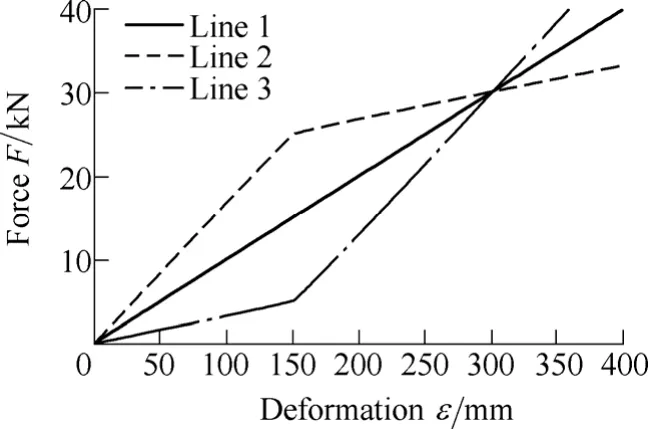
Fig.8.Restraint stiffness curves
So the convex restraint stiffness curve will be discussed next.Defining the base point as the point of inflexion in convex curves,the segment before the base point is called the front segment and the other segment is called the rear segment.Two kinds of convex curve are considered in this paper.The first type,with the same slope in the front segment,leads to similar ridedown efficiency of from 30%as the result of MATLAB program in Fig.9.The second type curve,with the same slope in the rear segment,has the different result that could be up to 45% (Line 1) in Fig.10.Consequently,the ridedown efficiency increases as the stiffness of the front segment increases,which means that the front segment slope affects the ridedown efficiency mostly.
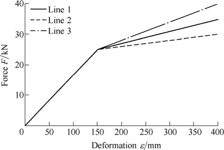
Fig.9.The first types of curves
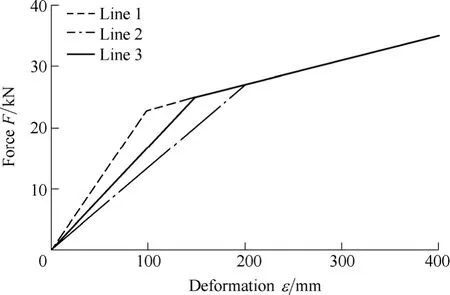
Fig.10.The second types of curves
3.4 Relationships between the ridedown efficiency and the occupant’s injury
The more ridedown efficiency,the more energy which is absorbed by the vehicle structure.As a result,the energy which needs to be dissipated by the restraint system is less.It is due to the fact that the summation of these two parts of energy is equal to the occupant’s initial kinetic energy.Even though,that does not mean the higher the ridedown efficiency the lower the occupant’s injury levels.As shown in Fig.11,the broken curves lead to higher ridedown efficiency than the real curve but it has a higher occupant acceleration level.These curves show that higher ridedown efficiency may lead to serious occupant injury.
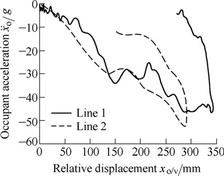
Fig.11.Ridedown curves from physical test
The response curve shown in Fig.12,has the highest ridedown efficiency,which is the result of the curve Line 1 shown in Fig.10.The design principle of the restraint system should aim for maximum ridedown efficiency and reducing the restraint force level through maximizing the use of the survival space (the maximum distance from the occupant chest to the steering wheel) as shown in Fig.13.If the remaining ridedown efficiency is unchanged,the maximum magnitude approaches a 0.22 m“maximum survival space”,and the peak occupant acceleration can be decreased.
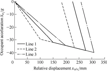
Fig.12.Ridedown curves from simplified model
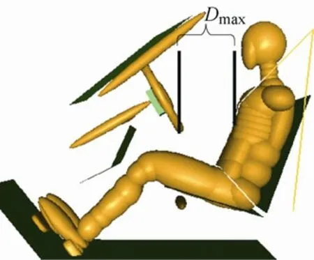
Fig.13.The maximum survival space
4 Optimization of Restraint System Based on the SMF
The optimal design based on SDOF of the A-class car was assessed by C-NCAP (China-NCAP) in this paper.The C-NCAP contains three tests:50 km/h FRB test,56 km/h frontal ODB test and the side impact test.The objective of the optimization is to reduce occupant chest acceleration and to get a rating point higher than 10 in the 50 km/h FRB test.
Given the maximum survival space of 0.22 m for this vehicle,shown in Fig.13 (Dmax) and the frontal impact pulse is shown in Fig.2.The rating point of driver chest is 0.27 m by CNCAP before optimization.
For the sake of cost,the belt pretentioner is not implemented in this restraint system,soδis added in the example.The main optimal parameters are the safety belt stiffness and the load limiter level.
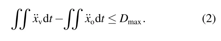
Applying the main Eq.(1),the factorKis the restraint stiffness and it can be achieved from the belt stiffnessk.Given the constraint conditions shown in Eq.(2),the force produced by the relative displacement should be limited by the load limiter levelL,and the relative displacement should be smaller thanDmax.
Note that the belt stiffness varies from 3% to 15% and the load limiter levels are 3 000 N,3 500 N,4 000 N,4 500 N.A program is worked out by MATLAB to do the circular calculation to find out the appropriate results.
Based on the results from the whole combination of load limiter level and belt stiffness (Fig.14),the appropriate ones can be determined,as shown in Table 1.
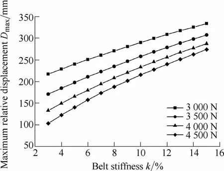
Fig.14.Calculation results
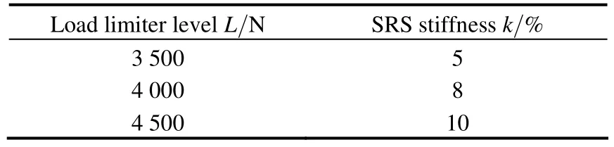
Table 1.Optimization results
Considering the real production of the belt,the best combination is 4 kN load limit and 8% belt stiffness.Under this situation,the ridedown efficiency is high and the relative distance calculated by the SDOF is very close toDmax.
It can lead to the lowest level of chest acceleration.The chest acceleration calculated by the SDOF is the broken curve,as shown in Fig.15.Then the validation with MADYMO and sled test was done.
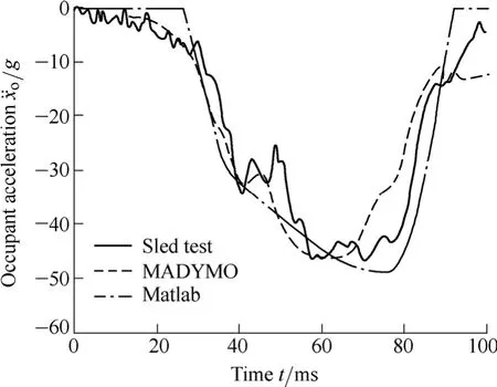
Fig.15.Three chest acceleration curves
A simulation model with the same restraint system parameter combination which was illustrated before is established by MADYMO and its result is shown in Fig.15.The sled test result is shown in the same figure.All the curves have high coherence with each other.The dummy injuries are shown in Table 2,and C-NCAP rating points are shown in Table 3.
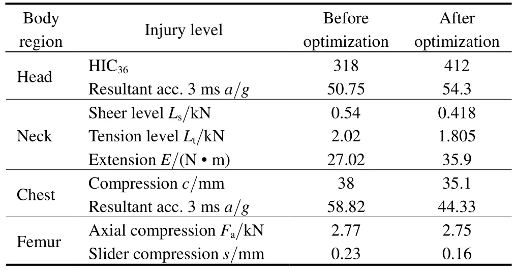
Table 2.Dummy injury level
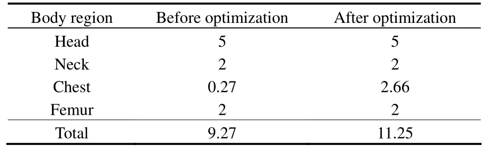
Table 3.C-NCAP rating points
The appropriate design of restraint system can reduce the occupant injury.The most important design parameters can be calculated quickly by the single degree freedom model in concept design.It is an effective and efficient method for ensuring system performance.
The SDOF still cannot predict the dynamic responses of other parts of the occupant body.In addition,the restraint stiffness,as the key design parameter,is not correlated to the belt stiffness directly.How to optimize the design of the airbag,steering column and knee-bolster is going to be investigated in a further study.
5 Conclusions
(1) The relationships between ridedown efficiency,the restraint stiffness and occupant injury are discussed based on the simplified vehicle-occupant model.Also,a conceptual design and optimization for the occupant restraint system of an A-Class car is conducted with the simplified model.The conclusions are:
(2) The“occupant-vehicle”model is a simplified model built from the mechanics relationship between the occupant,restraint system and the vehicle.The main characteristics of the occupant response can be reflected by this model.
(3) The shape of restraint stiffness curve can lead to different ridedown efficiency and the convex curve can lead to higher ridedown efficiency than other shaped curve in the same vehicle crash event.
(4) The higher ridedown efficiency means more occupant energy absorbed by the vehicle,but does not mean a lower occupant injury level.A proper restraint system design in protecting the occupant depends on two aspects.On one hand the restraint system can lead to high ridedown efficiency,on the other hand,and the restraint system should use the survival space effectively.
[1]ZHANG Junyuan,LI Dongjun,BI Ying,et al.Optimization of vehicle side curtain airbag module based on computer aided engineer[J].Chinese Journal of Mechanical Engineering,2009,22(4):521–527.
[2]ZHANG Junyuan,ZHANG Min,DING Rufang.Key techniques of multi-body modeling of occupant restraint system of vehicle side impart[J].Chinese Journal of Mechanical Engineering,2009,19(3):393–400.
[3]OWENS C,HASSEL E V,UNGER M,et al.Frontal system optimization with MADYMO and mode frontier[G].SAE Paper2009-26-005.
[4]VANGIPURAM R,LONG L.Truong H.et al,Parameter design based FEA correlation studies on automotive seat structures[G].SAE Paper2008-01-0241.
[5]PARK S D,PYUN J K,CHOI B Y,et al.Seat common frame design optimization[G].SAE Paper2010-01-0390.
[6]KHANNA S.Improving vehicle performance in offset deformable barrier crash as per ECE R94 via computer aided engineering[G].SAE Paper2009-01-0351.
[7]KANG S,FEUSTEL J,BARNES E.Driver airbag linear impactor dynamic testing method and data analysis[G].SAE Paper 2006-01-1436.
[8]EVANS N C,FURTON L M,COK D A.Occupant energymanagement technique for restraint system analysis and design -theory and validation[G].SAE Paper922082,1992.
[9]BONELLO K J.Occupant energy management technique for restraint system analysis and design Understanding the physics of the system[G].SAE Paper922083,1992.
[10]HUANG M,LAYA J,LOO M.A study on ride-down efficiency and occupant responses in high speed crash test[G].SAE Paper950656.
[11]MACMILLAN R H.Dynamics of vehicle collisions[M].London,UK:Inderscience Enterprises Ltd.,2002.
[12]ZHANG Xuerong,LIU Xuejun,CHEN Xiaodong,et al.Development and test validation of safety belt restraint system for frontal impact[J].Automotive Engineering,2007,29(12):1 055–1 058.
[13]SAUNDERS J,STASHNY A,WIACEK C.Relationship between frontal stiffness and occupant compartment intrusion in frontal crash tests[G].SAE Paper2008-01-0815
[14]ROSE N A,STEPHEN J,FENTON,et al.Crush and conservation of energy analysis:toward a consistent methodology[G].SAE Paper2005-01-1200.
[15]WUJianping,BLKHUL S,GUY S,et al.An impact pulse-restraint energy relationship and its applications[G].SAE Paper2003-01050,2003.
[16]PATHARE R,LOKHANDE A,VOGEL G,et al.Material model development of an energy absorbing foam for occupant safety[G].SAE Paper2009-26-088.
Biographical notes
ZHANG Junyuan,PhD,born in 1965,is a full-time professor atJilin University,China.She received her BSc,MSc and PhD degrees in Automobile Engineering fromJilin University,China,in 1985,1990,and 2003,respectively.She worked as an engineer atR&D Centre FAW,China,from 1985 to 1995,and visited toFord Motor Co.,U.S.,in 1998.Her research interests include Auto-Body design and vehicle passive safety.
Tel:+86-431-85 095584;E-mail:junyuan@jlu.edu.cn
MA Yue,born in 1988,received her BSc in Automotive Engineering fromJilin University,China.At present,she is an MSc candidate atJilin University,China.Her research focused on vehicle passive safety,and restraint system design and optimization methods particularly.
E-mail:mayue2011422080@126.com
CHEN Chao,born in 1985,received his BSc and MSc degrees in Automotive Engineering fromJilin University,China,in 2008 and 2011,respectively.His research focused on vehicle passive safety.
E-mail:robin965371@sohu.com
ZHANG Yan,born in 1985,received her BSc and MSc degrees in Automotive Engineering fromJilin University,China,in 2007 and 2009,respectively.She is engaged in vehicle passive safety.
E-mail:66136576@qq.com