Computational and Experimental Investigation on Aerodynamic Characteristics of Terminally Sensitive Projectile with S-C Shaped Fins
2012-07-25HUZhipeng胡志鹏LIURongzhong刘荣忠GUORui郭锐
HU Zhi-peng(胡志鹏),LIU Rong-zhong(刘荣忠),GUO Rui(郭锐)
(ZNDY of Ministerial Key Laboratory,Nanjing University of Science and Technology,Nanjing 210094,Jiangsu,China)
Introduction
Traditional terminally sensitive projectile uses a parachute to realize stable scanning movement.In this case,there are some adverse factors,such as large volume,low terminal velocity,great effect of crosswind on it and enemy interference and so on.The terminally sensitive projectile with S-C shaped fins has the notable advantages over the traditional terminally sensitive projectile,including lower sensitivity to crosswind,mitigation of deployment problems,and higher falling velocity.The terminally sensitive projectile with S-C shaped fins realizes a stable scanning movement under asymmetrical aerodynamic force and moment generated by asymmetric fin configuration and fin structure.The shape,dimension and installation configuration of fins determine the stable scanning parameters of terminally sensitive projectile.
The research on the stable scanning mechanism and aerodynamics of terminally sensitive projectile had been carried on for several years.SHU[1]analyzed the scanning motion theorem of dual-wings terminally sensitive projectile by calculating the ballistic equation based on mass and aerodynamics asymmetry.WANG[2]analyzed the scanning motion process and the effect of wing structure on the stable scanning movement parameters.A semi intelligent artillery munition system named BONUS[3]was under development at Swedish Ordnance in Karlskoga for wind tunnel test.Nadal-Mora developed a rotary wing Pararotor for the purpose of measuring atmospheric properties around airports.A semi empirical aerodynamic model in condition of low aspect ratio,low Reynolds number and rotor in autorotation and a stability model have been developed[4-6].First Austin Howard[7]investigated the potential advantages of the rotary wing decelerator technology,assessed the aerodynamic modeling tools,and quantified the performance of dual wing decelerator through wind tunnel experimentation.ZHOU[8]designed the aerodynamic shapes of terminally sensitive projectile with axial and radial type wing structures and tested it at smaller attack angle in low speed wind tunnel.It is difficult to develop a theoretical method to obtain the accurate aerodynamic parameters of terminally sensitive projectile because of special shape,flight status at high attack angle[9]and very complex flow field characteristics.The main method to investigate the aerodynamic characteristics is low speed wind tunnel experiment.The wind tunnel experiment especially in multiple operating conditon.In recent years,with the development of computational fluid dynamics[10],it is possible to use the numerical methods to solve this type of problem.This paper uses computational fluid dynamics to research the aerodynamic characteristics of terminally sensitive projectile with S-C shaped fins,and free flight experiment was performed for studying its dynamic aerodynamic characteristics.
1 Numerical Calculation
1.1 Aerodynamic Shape
In order to form stable scanning movement,the aerodynamic shape of terminally sensitive projectile is required to fit in with these basic conditions:to provide sufficient drag to balance projectile weight,to generate rolling moment and keep stable rolling velocity,to offer pitch and yaw moments.Based on these principles,the aerodynamic shape of terminally sensitive projectile was designed,as shown in Fig.1.
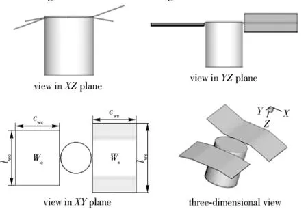
Fig.1 Sketch of aerodynamic shape of terminally sensitive projectile with S-C shaped fins
The two fins are installed on the bottom of the flatnosed cylinder body at angle 90°.Part of body and fin symbols are defined as follows:the diameter of cylinder isd,the height of the cylinder ish.The S shaped fin is defined asWs,wingspan aslws,wing chord ascws.The C shaped fin is defined asWc,wingspan aslwc,wing chord ascwc.This paper discusses the effect of wing aspect ratio on aerodynamic characteristics.The dimensions of model used for calculation are given in Tab.1.

Tab.1 Model dimensions mm
1.2 Flow Field Grid Generation
The density distribution of grid is controlled according to the aerodynamic characteristics of terminally sensitive projectile and the flow field characteristics.The fines are taken as the primary locations of aerodynamic drag and moment acting on layout boundary layer mesh on the surface to control and improve the mesh quantity.Because the junction structure of body and fins is extraordinary complex,the unstructured grid is generated in order to improve the calculation accuracy for mesh adaptive in the calculation.The distance of external flow-field from the model centroid is 15 times longer than the body length,and is of 10 times longer than the diameter of projectile.The calculated flow field is shown in Fig.2.

Fig.2 Flow field grid around the projectile
1.3 Flow Field Calculation
Control equation uses three-dimensional Reynolds Averaged Navier-Stokes equation in the form of integral considering a viscous term

where
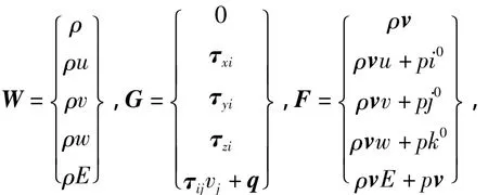
whereH,v,E,p,τ,h,qandρare mean source term,speed term,total quality,pressure,viscous stress tensor,specific enthalpy,heat flow and density,respectively.
The discrete method uses a finite volume method,and the equation of motion uses a second-order upwind scheme.Turbulence model uses the standardk-εmodel.The outflow field simulation has a better accuracy by using the compressible gas model compared with the incompressible gas model.In this case,the flowMais less than 0.1,the flow field is treated as an incompressible flow,and the boundary is velocity inlet and outflow.WhenMais less than 0.1 the flow is treated as incompressible flow and is solved by using the incompressible ideal gas model and the discrete solver.
2 Simulation Result and Discussion
2.1 Surface Pressure Distribution
The surface pressure distributions of the two models at attack angle of 0°in Fig.3 show that the two models have similar pressure distribution.High pressure region mainly presents on the top surface of cylinder body,at the upwind side of the fins and the junction of body and fins.Low pressure areas are mainly located in the side surface and tail of cylinder body and the leeward side of the fins.
Airflow is blocked and compressed when it comes to the surface of cylinder top.The flow velocity is reduced to zero and formes a stationary point.Hence a high pressure is generated around the cylinder top surface center.The flow bypasses the warhead combined with far field flow reduced by the wing and formed a stationary point and a large area of high pressure generated around the center of the fins.With the mutual interference of the body and fins,the flow turns over at the fin junction and generates a high pressure area at the conjunction of the body and fins.Due to the vortex at the side surface front the wing making this area form low pressure.due to the expansion of the air and speed up velocity at the junction of the top of the cylinder and the cylindrical surface and convex wings,form the area of low pressure.
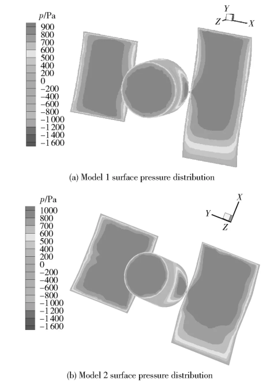
Fig.3 Surface pressure distributions
2.2 Drag Coefficient
Figure 4 shows the drag coefficient curves varying with attack angle at 30 m/s.The two models have the large values of drag coefficient that can offer efficient drag force to keep balance of the model gravity.
The drag coefficient curves of the two models have similar change trend.The drag coefficient decreases and then increases with the increase in the absolute value of attack angle from 0°to 30°.The drag coefficient value at 30°is larger than that at 0°.
As seen from Fig.4,the drag coefficient changes significantly with the wing aspect ratio.The drag coefficient increases with the increase in wing aspect ratio.The drag coefficient of model 1 is 50%less than that of model 2.The drag coefficient of model 1 changes with attack angle sharply than model 2.
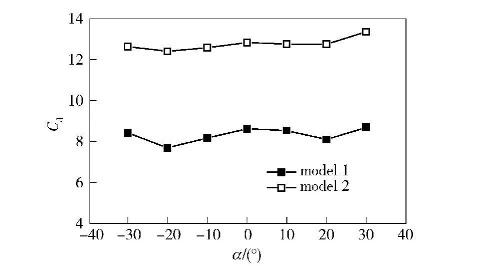
Fig.4 Drag coefficient curves
2.3 Lift Coefficient
Figure 5 shows the lift coefficient curves varying with angle attack.The lift coefficient curves of the models have similar varying trend.As the attack angle increases from negative to positive,the lift coefficient is a negative linear slope.With the increase in the value of the attack angle,the absolute value of lift coefficient of model 2 is larger than that of model 1.
Fig.5 Lift coefficient curves
2.4 Rolling Moment Coefficient
Figure 6 shows the rolling moment coefficient curves varying with angle attack.The rolling coefficient gradually decreases with the increase in attack angle.The rolling coefficient of model 2 is bigger than that of model 1,and presents a significant declining trend.
3 Free Flight Aerodynamic Characteristics
Fig.6 Roll coefficient curves
The simulation result shows the effect of wing aspect ratio on the static aerodynamic characteristics.In order to study the aerodynamic characteristics under dynamic conditions,a free flight of full size model test was carried out.
3.1 Experimental Design
An experimental model is shown in Fig.7.The body of model is a flat cylinder with radius of 56 mm,and height of 135 mm,mass 4.2 kg.Two fins are installed on it,which one is S shape and the other is C shape.
Fig.7 Experimental models of terminally sensitive projectile with S-C shaped fins and experimental design
The model was dropped from a 100 m height tower to the ground.It can be seen from Fig.7 that the distance between two landmarks is known.The flight process was recorded by using the high speed video system for the analysis of model falling speed and attitude motion.A rotation data recorder inside the model was used to record the rotation of model during flight.
3.2 Test Result and Discussion
According to the given data,such as initial trajectory height and height of the landmarks,the drag coefficient of the model during dropping can be found by using the least square method to fit the free flight trajectory curve with ballistic interval data get from high speed video.The motion processes of model 1 and model 2 were simulated to obtain the ballistic and speed curves.
Figure 8 shows the fitting curves of ballistic trajectory.The calculated drag coefficients of model 1 and model are 2 6.16 and 7.33,respectively.
Fig.8 Experimental and simulation ballistic curves
Figure 9 shows the speed curves.The data points in Fig.9 is the tested average speed values of two adjacent landmarks when model flight through landmark B to A.
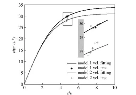
Fig.9 Experimental velocity and theory velocity
It can be seen from Fig.9 that the model velocity reaches a steady state after flying for 10 s and the stability speed is 30-45 m/s.The experimental result shows that this fin structure offer a better effect for reducing the velocity and can balance the drag of the body's own gravity.
The speed fitting curve in Fig.9 also shows that model 1 has a high velocity value.While it takes more time to form the final stability speed than model 2.
Table 2 lists the experimental results of drag coefficients and rolling coefficients of the models at attack angle of 30 degrees.model 1 - 3 is the third experimental result of model 1.
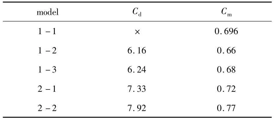
Tab.2 Aerodynamic coefficients of test model
The curve-fitting solutionCdin Tab.2 is consistent with the simulation results,hence,the simulation results can be considered to reflect the model aerodynamic characteristics.
Cdvalue calculated from ballistic fitting curve is smaller than the simulation result.That is due to an included angle between the model axis and the velocity vector during flight.The angle can be seen from Fig.7.In fact,the angle is the scanning angle of terminally sensitive projectile.
Model free flight shows that scanning angle changes in a very large range from the initial state to the steady state.It can be found from the simulation results that the drag coefficient of the model decreases significantly at a high attack angle.Hence the fitting result is closed to the simulation results at high attack angle.
4 Conclusions
By comparing the simulation results with the experimental data,the simulation results basically reflects the aerodynamic characteristics of terminally sensitive projectile.The drag coefficient,lift coefficient and rolling coefficient decrease with the decrease in fin area.The wing aspect ratio has a significant influence on the rolling coefficient.
There are some differences between static and dynamic aerodynamic characteristics.The model has cylinder body with small length to diameter ratio,and the fin structure is very complex.The airflow on the fins seriously interferes with the model.Therefore,It is needed more wind tunnel experiments and numerical simulation study.
[1]SHU Jing-rong,The study on the large attack angle scanning characteristic of asymmetric terminal sensing submunition and its application[D].Nanjing:Nanjing University of Science and Technology,2004.(in Chinese)
[2]WANG Ai-zhong.Study on non-parachute terminal sensitive projectile stable scanning characteristics[D].Nanjing:Nanjing University of Science and Technology,2008.(in Chinese)
[3]Karlsen L,Borgström D,Paulsson L.Aerodynamics of a rotating body descending from the separation position of an artillery munition shell,AIAA-91 - 0870-CP[R].America:American Institute of Aeronautics and Astronautics,1991.
[4]Vicente Nadal Mora,Joaquín Piechocki.Experimental research on a vertically falling rotating wing decelerator model,AIAA 2007 -2538[R].America:American Institute of Aeronautics and Astronautics,2007.
[5]Vicente Nadal Mora,Ángel Sanz-Andrés,Álvaro Cuerva.Model of the aerodynamic behavior of a pararotor[J].Journal of Aircraft,2006,43(6):1893 -1903.
[6]Vicente Nadal-Mora,Ángel Sanz-Andrés.Stability analysis of a free-falling pararotor[J].Journal of Aircraft,2006,43(4):980-986.
[7]First Austin Howard,Donald Elger.Rotary wing decelerators for miniature atmospheric entry probes,AIAA 2009-2996[R].America:American Institute of Aeronautics and Astronautics,2009.
[8]ZHOU Zhi-chao,ZHAO Run-xiang.Experimental investigation on aerodynamic characteristics of smart submunitions with different tail fins[J].Journal of Experiments in Fluid Mechanics,2010,24(4):52-55.(in Chinese)
[9]SHU Jing-rong,JIANG Sheng-ping,LI Ming-jun,et al.Force and moment analysis for double-win terminal sensing ammunition without parachute at stable-scanning stage[J].Journal of Ballistics,2010,22(2):48 - 51.(in Chinese)
[10]WANG Fu-jun.Computational fluid dynamics:the theorem and application CFD software[M].Beijing:Tsinghua University Press,2004.(in Chinese)
杂志排行

Defence Technology的其它文章
- Velocity Correction and Measurement Uncertainty Analysis of Light Screen Velocity Measuring Method
- Environment Adaptability Evaluation for Buffering Airbag of Heavy Equipment During Airdrop Landing
- Research on Hybrid Power System with Dual Stator-winding and Its Decoupled Control Strategy
- Research on Top-layer Planning and Overall Design Project Decision of Weapon System Based on Analytic Hierarchy Process
- Research on Matching Relationship Between Number of Initiation Points and Charge Diameter
- Experimental Investigation on the Ballistic Resistace of Metal Plates Subjected to Impact of Rigid Projectiles