Flow Characteristics of Expansion Energy Used Pneumatic Booster
2012-01-20SHIYanCAIMaolinXUWeiqingandJie
SHI Yan ,CAI Maolin, *,XU Weiqing ,and LÜ Jie
1 School of Automation Science and Electrical Engineering,Beihang University,Beijing 100191,China 2 National Quality Supervision and Inspection Center of Pneumatic Products,Fenghua 315500,China
1 Introduction
Because of its compact structure,small size,no external power supply,etc,pneumatic booster is widely used in locally pressure-boosting applications where there is a need for a small amount of higher pressure air[1-2].The most common booster is called input pressure reduced (IPR)booster.The output pressure is set by adjusting the input pressure of the driving chambers by a regulator,such as the VBA series of boosters by SMC Corporation[3].With the development of energy-saving technologies of the pneumatic system,the importance of booster has become more and more obvious[4-5].However this type of booster has its own shortages,such as its small output flow,when the boosting ratio is higher,the shortage becomes more distinct.Furthermore,its energy efficiency is not high,which restricts its applications[6-8].
Recent research on pneumatic boosters mainly focused on the factors that influence the characteristics of the boosters[9-11].For example,the change lows of the booster's performance during the gas injecting process was studied experimentally by WANG,et al[10],and the effects of the inlet pressure,the pressure and instantaneous flow rate of driving air were obtained in comparison method.
Furthermore,some new kinds of pneumatic booster structures were designed,but the efficiency and flow of these boosters are still not improved sufficiently[7,12-14].For example,one new kind of pneumatic booster,expansion type booster,was proposed by TAKEUCHI,et al[7],as shown in Fig.1,it is composed of a regulator,a piston,driving chambers,boosting chambers,expansion chambers,two reversing valves,and four check valves,the expansion power of compressed air in driving chamber can be used in expansion chambers,and the efficiency is higher than the ordinary IPR booster by 10%.However,energy loss in the regular is not avoided.In addition,the structure is so complex that this type booster has not yet been popularized.
In this paper,firstly,based on the working principle of the IPR booster,one new type of booster,Expansion Energy Used pneumatic booster (EEU booster),was
proposed which made use of the expansion power of the compressed air in driving chambers to improve output flow and power.Based on the analysis of working principle and structure of both boosters,the mathematical model of the boosters was set up,using the software MATLAB/simulink for modeling simulation,and movement characteristics of the piston,variations of the air pressure in the boosting chambers and driving chambers,and characteristics of the output flow of the boosters were obtained for analysis of principle of elevation of output flow.
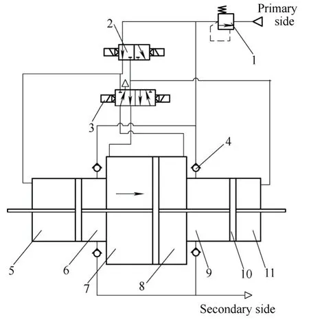
Fig.1.Structure of pneumatic booster
There are several definitions that should be introduced namely,the Terminal Pressure,the piston stroke-set,the output flow efficiency,the input pressure,the optimum work state and the boosting ratio.Firstly,the working characteristics of the two kinds of boosters are directly influenced by the air pressure in the working driving chambers.Therefore,the terminal pressure (pd-T) is defined as the air pressure in the working driving chamber when the piston reaches its terminal position.Secondly,the piston stroke of the EEU booster,when the working driving chamber stops charging air,is defined as the piston stroke-set (xset),which determines the terminal pressure(pd-T).Thirdly,the ratio of the output flow and the total input flow of the boosters is defined as the output flow efficiency.In addition,the air pressure which was charged into the driving chamber of the IPR booster is defined as the input pressure (pd-i) of driving chamber.Furthermore,the state when the piston stroke-set of the EEU booster is set longer,while the output flow stays approximately constant,is defined as the optimum work state.Finally,the ratio between the output pressure and the input pressure is defined as the boosting ratio.
Through simulation research of the two types of boosters,the relationship between the terminal pressure of the air in the working driving chamber and the piston stroke-set of the EEU booster,as well as the relationship between the terminal pressure and the input pressure of air in the working driving-chamber the IPR booster,were obtained.Moreover,through simulation and experimental study of the flow characteristics of the two kinds of boosters,it is clear that the flow of the air exported by the EEU booster is larger than that by the IPR booster;however the output flow efficiency of the EEU booster is almost the same as the IPR booster.The research lays the foundation for optimistic of the EEU booster.
2 Working Principle of Pneumatic Boosters and Mathematical Modeling
2.1 Working principle of pneumatic boosters
2.1.1 IPR pneumatic booster
A typical IPR booster,as shown in Fig.2,is composed of a regulator,a piston,driving chambers,boosting chambers,a reversing valve,and four check valves.
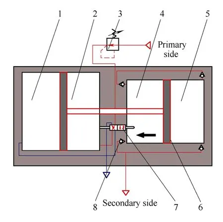
Fig.2.Structure of the IPR pneumatic booster
When the driving chamber A is connected to the atmosphere through the reversing valve,part of the compressed air charged from the primary side (the suction side,as shown in Fig.2) flows directly into the boosting chamber B while the remaining air flows into the driving chamber B through the regulator and the reversing valve successively.As a result of the regulator,the air pressure in driving chamber B will be reduced.The compressed air in boosting chamber B and driving chamber B drives the piston to move toward the left.The air pressure in boosting chamber A increases until the pressure is higher than that of the secondary side (the exhaust side,as shown in Fig.2).Thereafter,the higher-pressure compressed air is discharged from the chamber A to the secondary side.
When the piston reaches its travel destination and impacts the rod of the reversing valve,the reversing valve changes its state,and causes the air in the driving chamber B to flow to the atmosphere.The air charged from the primary side flows directly into boosting chamber A and flows into the driving chamber A through the regulator and the reversing valve.The air in the boosting chamber A and the driving chamber A then drives the piston to move toward the right while the air pressure in the boosting chamber B increases.Finally,the higher-pressure compressed air in the boosting chamber B is discharged to the secondary side.The booster continues to deliver higher pressure compressed air by repeating the process discussed above.
2.1.2 EEU pneumatic booster
A typical EEU booster,as shown in Fig.3,is composed of a controller,four magnetic switches,two magnetic rings,two solenoid valves,a piston,two driving chambers,two boosting chambers,and four check valves.The input flow of the booster is controlled by the controller.
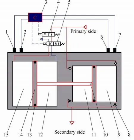
Fig.3.Structure of the EEU booster
When the piston reaches its left travel destination,the solenoid valve A and the solenoid valve B changes their positions.This connects the driving chamber B to the atmosphere and allows the compressed air,charged from the primary side (the suction side,as shown in Fig.3),to flow into the boosting and driving chambers A.The compressed air in these chambers drives the piston toward the right.The air pressure in the boosting chamber B increases until the pressure is higher than that of the secondary side (the exhaust side,as shown in Fig.3).Thereafter,the higher-pressure compressed air is discharged from the boosting chamber B to the secondary side.
When the piston moves near the magnetic switch C,the solenoid valve A changes its position and the compressed air,charged from the primary side,stops flowing into the driving chamber A.Depending on its expansion energy,the compressed air in driving chamber A keeps driving the piston until it arrives at its right travel destination (namely,near magnetic switch D).This allows part of the expansion energy of the air in the driving chamber A to be used.The positions of the solenoid valve A and the solenoid valve B are controlled by the controller.The air in driving chamber A flows to atmosphere while the air,charged from the primary side,flows into the boosting and driving chambers B.The air in these chambers then drives the piston toward the left which causes the air pressure in the boosting chamber A to increase.Thereafter,higher-pressure compressed air in the boosting chamber A is discharged to the secondary side.
When the piston moves near the magnetic switch B,the solenoid valve A changes its position and the compressed air,charged from the primary side,stops flowing into the driving chamber B.Part of the expansion energy of the air is therefore used to drive the piston until it arrives at its left travel destination (namely,near the magnetic switch A).Thereafter,the solenoid valves A and B change their positions and the air in the driving chamber B is exhausted to the atmosphere.The booster delivers higher pressure compressed air by repeating this process.
Through the description above,it can be seen that,the structure of the IPR booster is more complicated than that of the EEU booster,but the distinct shortage of the EEU booster is that the controller needs external power supply.
2.2 Mathematical modeling of working principle of pneumatic boosters
To facilitate this research,the following assumptions are made.
(1) The working fluid (air) of the system follows all ideal gas laws.
(2) There is no leakage between the chambers,the area of the piston rod end is too small to be considered,and the effective areas of all intake and exhaust ports are the same.
(3) Supply temperature is equal to atmosphere temperature.
(4) The flow of air moving into and out of the chambers is a stable one-dimensional flow that is equivalent to the flow of air through the nozzle contraction.
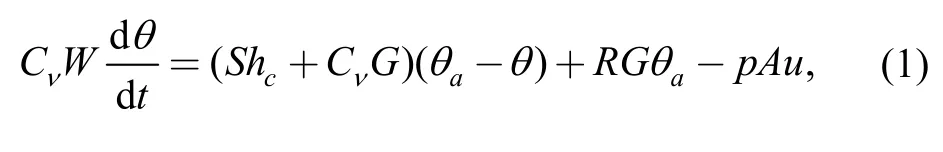
2.2.1 Energy equation
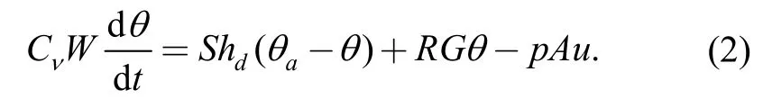
Because there is no leakage in either chamber,the chambers do not charge and exhaust air simultaneously.Consequently,the energy equation for the discharge and charge side of each chamber can be illustrated by the following equations:
2.2.2 Equation of continuity
From the law of mass conservation,air mass can be given as
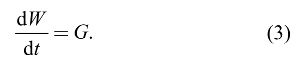
Air mass flow is calculated from the flow equation,which is described later on.
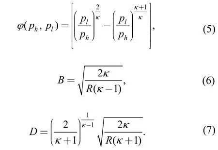
2.2.3 Flow equation
According to the ratiopl/ph,the flow equation for the flow through a restriction can be written as follows[15]:
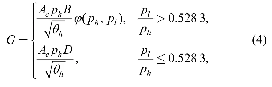
where
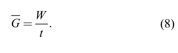
The average output flow of the booster is the average value of one period:
2.2.4 Motion equation
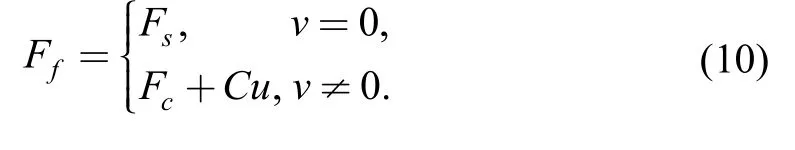
The velocity of the piston is calculated from Newton's second law of motion.In this paper,the friction force model is considered to be the sum of the Coulomb friction and viscous friction.The viscous friction force is considered to be a linear function of piston velocity.The forces on the piston of the booster are shown in Fig.4.
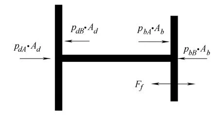
Fig.4.Forces on the piston of the booster
The right side was considered to be the positive direction of the vector.The motion equation of the piston can be given by the following equation:
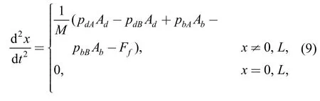
where
2.2.5 State equation
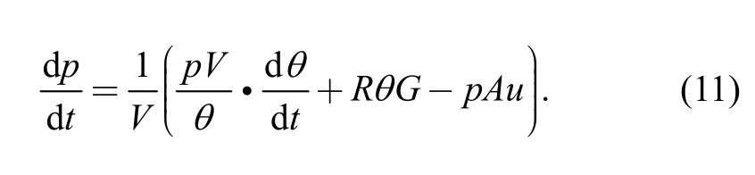
Pressure changes in the air in each chamber can be obtained by deriving the state equation of ideal gases:
3 Simulation and Experiment of Pneumatic Boosters
3.1 Experimental apparatus
The experimental apparatus shown in Fig.5 consists of a regulator (IR3020-03BC) by SMC,a booster,a PLC(S7-220) by Siemens,a flow sensor (APM-450) by Tokyo Meter,a tank,a throttle valve (AS3001F) by SMC,a data acquisition card (USB-4711A) by Advantech.The booster,which can be used as the IPR booster and the EEU booster through adjusting its structure,is composed of a series of products by SMC such as two cylinders (CDQ2B100-100D),a solenoid valve (VQD1151U-5L),a regulator(IR3020-03BC),a floating connector (JAL100-26-150),four magnetic switches (A73),and four check valves(AKH08).
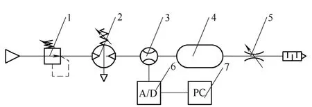
Fig.5.Configuration of experimental apparatus
Schematic of the IPR booster used in this paper is shown in Fig.6.The adopted flow sensor is an Air Power Meter that can measure the pressure,flow and temperature of compressed air simultaneously.The uncertainty of the pressure,flow and temperature is 0.1%,±1% F.S.and 0.1 °C,respectively[16-17].
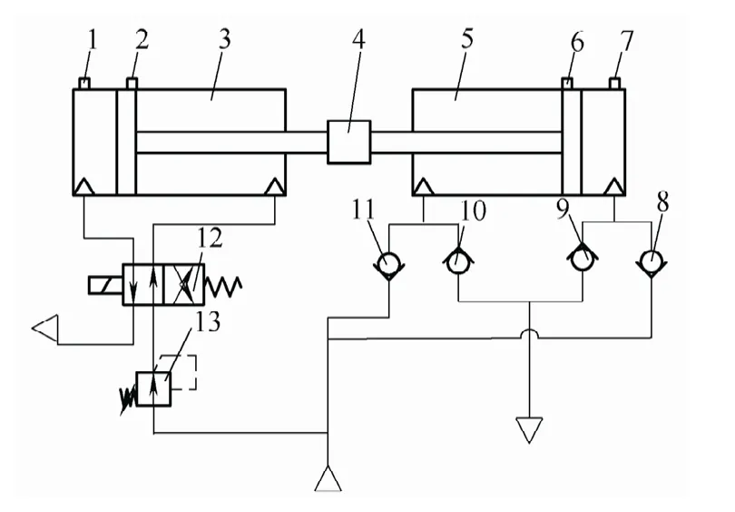
Fig.6.Schematic of pneumatic booster
In this experiment,we first opened the compressed air source,adjusted the regulator and set the pressure to the fixed value.Next,we adjusted the throttle valve,making sure that air was exhausted from the tank steadily,and the pressure of the air was approximate to the fixed value.The last procedure was data acquisition and preservation.
3.2 Simulation of pneumatic boosters
According to the Mathematical model above,the software MATLAB/simulink was used for modeling simulation,through analysis of the simulation results,the main dynamic characteristics of the boosters were obtained.
The pressure of the air source and the output of the boosters were set at 0.6 MPa and 0.8 MPa,respectively.The piston stroke-set of the EEU booster was 0.06 m,and the input pressure of the driving chamber of the IPR booster was 0.33 MPa.Figs.7(a) and 7(b) depict the characteristics of the piston motion of the two kinds of boosters.Figs.7(c) and 7(d) illustrate the pressure fluctuations of the driving chamber and the boosting chamber respectively while Fig.7(e) shows the output flow of the two kinds of boosters.
As shown in Fig.7,characteristics of the two kinds of boosters change periodically,when the piston reaches its travel terminal,the pressure of one driving chamber descend to the atmosphere pressure,and the pressure of another driving chamber ascend to the input pressure rapidly.Therefore,the piston move speedily near the travel terminal,and the pressure of the boosting chamber elevates swiftly,then the pressure of the driving chamber drops slowly,and the velocity of the piston starts to decline.However,the pressure of the boosting chamber continues to go up,and peaks when the piston near the middle of its stroke.Due to higher pressure of the driving chamber of the EEU booster than the pressure of the driving chamber of the IPR booster at that time,the piston of the EEU booster moves faster than that of the IPR booster,the output flow of the EEU booster is larger than that of the IPR booster.
With the rise in the input flow of the IPR booster,the pressure of the driving chamber and the boosting chamber tends to be constant,and the velocity of the piston slows down and remains steady.
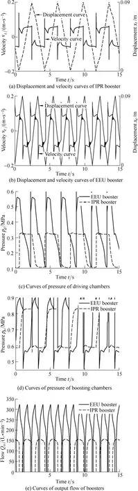
Fig.7.Simulation curves of the two kinds of boosters
As far as the EEU booster is concerned,when the driving chamber stops to charge air,depending on its expansion energy,the compressed air in the driving chamber keeps driving piston,until the piston arrives to another travel terminal,and in this moment,the pressure of the air in the driving chamber is the terminal pressure in the driving chamber of the EEU booster,which is the same as the terminal pressure in driving chamber of the IPR booster.During this process,the pressure of the driving chamber slumps sharply,meanwhile,the boosting chamber exhausts higher-pressure air tremendously,and the pressure of the chamber falls swiftly and accordingly after a slight rise,the velocity of the piston decreases dramatically.
The pressure of the driving chamber of the EEU booster all along being higher than or equal to that of the driving chamber of the IPR booster.Furthermore,the input flow of the EEU booster and the IPR booster are the same.Therefore,in the case of the same amount of input flow,the velocity of the EEU booster piston is more rapid than that of the IPR booster piston,and the output flow of the EEU booster is higher than that of the IPR booster[8].
3.3 Flow characteristics of the boosters
When caliber of intake and exhaust port is 2.5 mm,series of the piston stroke-set of the EEU booster and the input pressure of the driving chamber of the IPR booster were set,through simulation,the terminal pressure of the EEU booster and the IPR booster were obtained,as shown in Figs.8 and 9.
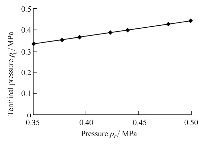
Fig.8.Curves of the terminal pressure of the IPR booster
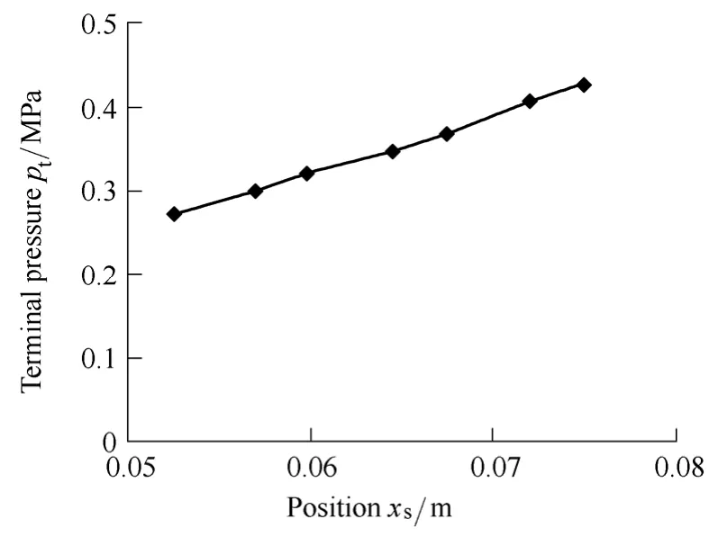
Fig.9.Curves of terminal pressure of the EEU booster
As can be seen from Fig.8 and Fig.9,firstly,the relationship between the input pressure of the driving chamber of the IPR booster and the terminal pressure in the driving chamber is approximately linear.Secondly the higher the input pressure of the driving chamber of the IPR booster is,the higher the terminal pressure of the air in the driving chamber is.Thirdly,the terminal pressure in the driving chamber of the EEU booster goes up steadily with an increase in the piston stroke-set[8].
The supply and the output pressure are set at 0.6 MPa and 0.8 MPa,respectively.Experimental and simulation studies of two kinds of boosters were done,and the results are shown in Fig.10.
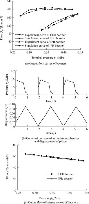
Fig.10.Simulation and experiment results of boosters
From Fig.10(a),it can be seen that:
(1) The uncertainty of the measured output flow is about±4.5 L/min,which is mainly determined by the uncertainty of the flow sensor,the fluctuations of the output flow,pressure and temperature[17].
(2) The mathematical model is verified and the experimental results correlate well with the simulation results.As can be seen from Ref.[18],the errors between the experimental and simulation results are mainly caused by pressure fluctuations of the air in the tank in the experiment.
(3) With an increase in the terminal pressure of the driving chamber,the output flow of the IPR booster increases stably.As the terminal pressure of the driving chamber increases,the output flow of the EEU booster rises and remains a near constant when the terminal pressure exceeds 0.35 MPa.In addition,when the terminal pressure of the driving chamber in the EEU and the IPR boosters are the same,the output flow of the EEU booster is greater than that of the IPR booster and the difference decreases with the rise in the terminal pressure.
When the piston stoke-set of the EEU booster is shorter than 60 mm and there is a rise from 0.27 MPa to 0.32 MPa in the terminal pressure of the driving chamber,its output flow increases from165.96 L/min to 193.61 L/min.When the piston stoke-set is longer than 60 mm,the output flow remains around 200 L/min.The primary reason is that the piston stroke is shorter during the expansion of the air in the working driving chamber.However,if the difference between the air pressure in the working driving chamber and the pressure of the air source is small,the velocity of the piston is only slightly influenced by the piston stroke-set.Moreover,because of the throttling effect of the intake and exhaust ports,the compressed air in the former working driving chamber is not completely discharged in time.This causes the pressure of air in the former working driving chamber to remain higher than the atmospheric pressure,which blocks the motion of the piston and reduces the output flow.When the piston stroke-set was set at 75 mm,it is clear from Fig.10(b) that the air pressure in the former working driving chamber had not declined to atmospheric pressure when the piston reached its travel terminal.
With regard to the IPR booster,the output flow rises stably with an increase in the terminal pressure of the driving chamber.The main reason is that there is no expansion process.The output flow is smaller and the throttling effects of the intake and exhaust ports are limited so that the output flow is mainly influenced by the terminal pressure of the driving chamber.
Fig.10(c) illustrates the relationship between the output flow efficiency and the terminal pressure of the air in the driving chamber of the two kinds of boosters,as can be seen that,the curve of the output flow efficiency of the EEU booster is almost coincided with that of the IPR booster,which means that,with the same the terminal pressure of the air in the working driving chamber,the output flow efficiencies of the two kinds of boosters are the same.
When the output pressure of the boosters was 0.8 MPa,and the pressure of air source was set at 0.5 MPa,0.55 MPa,0.6 MPa,0.65 MPa,0.7 MPa,0.75 MPa,and 0.8 MPa,under the optimum work state of the EEU booster,the output flow characteristics were studied.Fig.11 depicts relationship between output flow and boosting ratio of the two kinds of boosters under the optimum work state of the EEU booster.
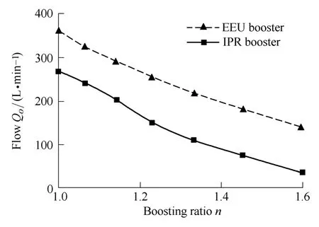
Fig.11.Relations of the output flow and the boosting ratio
It can be seen from Fig.11 that,under the optimum work state of the EEU booster,the output flow of the two kinds of boosters all declines with the rise of boosting ratio.Furthermore,the output flow of the EEU booster is higher than that of the IPR booster by 95 L/min approximately,and that is 1.4-4 times of that of the IPR booster.Especially when the boosting ratio is 1.6,the output flow is 4 times of that of the IPR booster.
4 Conclusions
(1) The pressure of the air in the EEU booster's driving chamber all along being higher than or equaling to that of the air in the IPR booster's driving chamber,and the input flow of the EEU booster and the IPR booster are the same.Therefore,in the case of the same amount of the input flow,the velocity of the EEU booster's piston is more rapid than that of the IPR booster's piston,and the output flow of the EEU booster is higher than that of the IPR booster.
(2) The simulation results and experimental results are in a good accordance,which verifies the mathematical model set up.
(3) The relationship between the input pressure of the IPR booster's driving chamber and the terminal pressure of the air in the driving chamber is approximately linear,the higher the input pressure of the IPR booster's driving chamber,the higher the terminal pressure of the air in the driving chamber.The terminal pressure of the air in the driving chamber of the EEU booster goes up steadily with the rise of the piston stroke-set.
(4) When the air source pressure and the output pressure are set at 0.6 MPa and 0.8 MPa,respectively,the output flow of the IPR booster ascends stably with increase of the terminal pressure of the air in the driving chamber.As the terminal pressure of the air in the driving chamber goes up,the output flow of the EEU booster rises,and remains almost constant when the terminal pressure is more than 200 L/min.In addition,when the terminal pressure of the air in the EEU booster and the IPR booster are the same,the output flow of the EEU booster is greater than that of the IPR booster,and the difference decreases with the rise of terminal pressure.The main reason is that the pressure in the boosting chamber of the EEU booster is higher than or equal to that of the IPR booster.
(5) When the output pressure is set at 0.8 MPa,under the optimum work state of the EEU booster,the output flow of the two kinds of boosters all declines with the rise of the boosting ratio.Furthermore,the output flow of the EEU booster is higher than that of the IPR booster by 95L/min approximately,and that is 1.4-4 times of that of the IPR booster.Especially when boosting ratio is 1.6,output flow is 4 times of that of IPR booster.
As an important element of pneumatic system,the EEU pneumatic booster was proposed;simulation and experimental studies verified that the output flow of the EEU booster is higher than that of the IPR booster.Besides,the mathematical model was set up,which laid an important foundation for optimization of the EEU booster,as the improvement,the factors,which influence the output flow characteristics,should be illustrated,and the optimized EEU booster will be designed and manufactured,the output flow and efficiency will be studied experimentally to motivate the development and advancement of the pneumatic booster.
[1]SMC (China) Co.,Ltd.Modern practical pneumatic technology(3)[M].Beijing:China Machine Press,2008.(in Chinese)
[2]CHEN Weiguo,DING Xusheng,GUO Xiangfeng.Study on principle and method of fluid pressurization technology[J].Machine Tool &Hydraulics,2001(2):54-55.(in Chinese)
[3]CAI Maolin.Theory and practice of modern pneumatic technology,sixth chapter:pressure regulator[J].Hydraulics Pneumatics &Seals,2008(1):53-58.(in Chinese)
[4]ONEYAMA N.Pneumatic manufacturer's attempts on energy saving[J].Hydraulics and Pneumatics,1996,27(3):372-377.
[5]SHI Yan,CAI Maolin,WANG Gaoping.Study on air-supplied with different pressure and locally pressure-boosting technology of pneumatic system[J].Machine Toll and Hydraulics,2010,28(9):57-59.(in Chinese)
[6]HAMAURA N,FUJITA T,KAGAWA T,et al.Characteristics analysis of pneumatic booster[C]//Proceedings of 1994 Autumn Symposium on Hydraulics and Pneumatics,Tokyo,Japan,1994:77-80.
[7]TAKEUCHI O,FUJITA T,KAGAWA T,et al.Characteristics analysis of expanding-type booster[C]//Proceedings of 1995 Autumn Symposium on Hydraulics and Pneumatics,Tokyo,Japan,1995:69-72.
[8]SHI Yan,CAI Maolin.Working characteristics of two kinds of air-driven boosters[J].Energy Conversion and Management,2011,52(12):3 399-3 407.
[9]WANG Haitao,XIONG WEI,LI Zhonghua.Research on the dynamic characteristics during boosting charge of gas booster[C]//Fifth National Conference on Fluid Power Transmission and Control &2008 Conference on hydraulic and pneumatic of Chinese Society of Aeronautics and Astronautics,Beijing,China,2008:362-366.(in Chinese)
[10]WANG Xu,WANG Hai-tao,XIONG Wei.Study on the characteristics of air driven gas booster based on experiments[C]//Proceedings of the Seventh International Conference on Fluid Power Transmission and Control,Hangzhou,China,2009:608-611.
[11]SHI Yan,CAI Maolin.Experimental study on working characteristics of pneumatic booster valve[C]//Proceedings of the 7th International Conference on Fluid Power Transmission and Control,Hangzhou,China,2009:511-515.
[12]DONG Fei,HE Guoqiang,ZHANG Zhiheng,et al.Design of pneumatic booster pump[J].Mechanical Science and Technology,2008,27(1):23-27.(in Chinese)
[13]WANG Xu.Study on new kind energy-saving gas booster[D].Dalian:Dalian Maritime University,2009.(in Chinese)
[14]SHI Yan,CAI Maolin.Study on efficiency and flow characteristics of two kinds of pneumatic booster valves[C]//Proceedings of the 2010 International Conference on Computer,Mechatronics,Control and Electronic Engineering,Changchun,China,2010:45-50.
[15]The Japan Hydraulic and Pneumatic Society.Manual of hydraulics and pneumatics[M].Tokyo:Ohmu Ltd.,1989.
[16]CAI Maolin,KAGAWA Toshiharu.Design and application of air power meter in compressed air Systems[C]//EcoDesign 2001:Second International Symposium on Environmentally Conscious De-sign and Inverse Manufacturing,Tokyo,Japan,2001:208-212.
[17]CAI Maolin,FUNAKI Tatsuya,KAWASHIMA Kenji,et al Development of air power meter for energy saving[C]//2003 Spring Symposium on Fluid Power System,Tokyo,Japan,2003:119-121.(in Japanese)
[18]SHI Yan,CAI Maolin,LIAO Pingping.Flow characteristics of pneumatic booster regulator[J].Journal of Harbin Institute of Technology,2010,42(12):2 013-2 016.
Biographical notes
SHI Yan,born in 1981,is currently a PhD candidate atSchool of Automation Science and Electrical Engineering,Beihang University,China.He received his bachelor degree fromYantai University,China,in 2005.His research interests include local pressure-boosting technologies of pneumatic system.
E-mail:yesoyou@163.com
CAI Maolin,born in 1972,is currently a professor and a PhD candidate supervisor atSchool of Automation Science and Electrical Engineering,Beihang University,China.His main research interests include the energy saving,measurement,simulation,and control of pneumatic system.
E-mail:caimaolin@gmail.com
XU Weiqing,born in 1984,is currently a PhD candidate atSchool of Automation Science and Electrical Engineering,Beihang University,China.He received his bachelor degree fromHunan University,China,in 2003.His research interests include pneumatic blowing system.
E-mail:xwqyyl@163.com
E-mail:ljpneu71@163.com