Study of Damage Characteristics during Fatigue by Acoustic Emission Techniques
2011-06-22
(Department of Naval Architecture,Dalian University of Technology,Dalian 116024,China)
Study of Damage Characteristics during Fatigue by Acoustic Emission Techniques
WANG Hui-jing,LIN Zhe
(Department of Naval Architecture,Dalian University of Technology,Dalian 116024,China)
Damage characteristics during fatigue and acoustic emission(AE)activities accounts for damage effect on material are studied.Damage evolution equation similar to the well-known Paris’formula is derived,as well as AE activities.A damage mechanics approach is applied to investigate AE activities.According to the damage effect on the size of plastic zone,a modified model for the plastic zone with damage is presented,which shows that the results of this proposed model are in a good agreement with experiments.Considered AE parameter as damage variable,the rule of damage evolution during AE activities is developed.Predictions by the proposed model are more consistent with the test data.And the damage evolution law is coincident with the experimental results.
Acoustic Emission;damage;plastic zone
Biography:WANG Hui-jing(1978-),female,Ph.D.student of Dalian University of Technology;
LIN Zhe(1957-),male,associate professor.
Nomenclature
Ae:the effective resisting area with damage;
A:the across section area without damage;
B:specimen thickness;
K′:stress intensity factor with damage;
σ′:the effective stress with damage,σ′=σexp β;
σy:the effective yield stress;
εy:the effective yield strain,εy=σy/E;
E:the Young’s modulus;
n:strain hardening exponent,0≤n≤1;
β:the damage variable representing the material section gradual reduction;R:the length of the plastic zone;
σ∞:the remote uniform stress;
Wy
p:the plastic strain energy density;
s0,S0:parameter;
γ,γ1:material constant,γ=2s0+1/n(high cycle),γ1=2s0+1/n(low cycle);

B″:material constant,B″=γB′/2(γ+1);
Cp:material parameter;
μ,α:coefficient.
1 Introduction
Acoustic emission(AE)is the class of phenomena where transient stress waves are generated by the rapid release of strain energy when the stress exceeds the yield strength σy,the materials undergo plastic deformation,crack initiation,growth or fracture.As a nondestructive evaluation technique for detecting active microscopic processes in the material,as well as crack initiation and propagation,AE has become a viable tool to monitor fatigue crack growth process.
Engineering materials usually fail as the results of plastic deformation or crack propagation proceeding by nonlinear stress and strain state within the local fields due to damage.The plastic zone size plays an important role in failure processes of materials.If it is possible to monitor plastic zone deterioration in real time by AE,the measured quantities could be used as indicators of the extent of fatigue damage.Recently,most attentions[1-3]are focused on the AE investigations of fatigue and fracture characteristics.Relatively little research,however,has been carried out in fatigue damage.By analyzing the damage effect on the size of plastic zone ahead of crack tip,a modified model for the plastic zone with damage is presented based on damage mechanics.Damage characteristics of material during fatigue and acoustic emission(AE)activities are studied.And a damage variable from AE parameter is presented.
2 Damage theory and derivation of damage model
2.1 Damage variable expression and fatigue damage evolution
Continuous damage variable D,characterized as the damage of material has been introduced by Robotnov[4],

And logarithm damage variable β to describe damage degree of material is used by

Comparison between Eqs.(1)and(2),it shows that D is approximately equal to β with slight damage,and a big error for them with serious damage.In this paper,damage variable is defined by Eq.(2).
Fatigue damage is mainly caused by plastic accumulation.Constitutive equation[5]derived from damage variable β for the high cycle fatigue is characterized as follows,

Regarded β and N as constants,by integrating Eq.(3)into one loading cycle,damage evolution equation for high cycle dβ/dN is obtained by

By integrating Eq.(4),under boundary conditions(if N=0,β=0;else N=Nf,β=1),assuming exp(γ )<1,damage variable expression is given by

For low cycle fatigue,the fatigue damage is related to plastic accumulation and hardening properties during fatigue cycles.Damage constitutive equation[5],introduced by hardening state variable G,G=G0h,assuming that G with power exponent function Δσ and N,for the low cycle fatigue is characterized as follows,

Regarded β and N as constants,by integrating Eq.(6)into one loading cycle,damage evolution equation for low cycle dβ/dN is obtained by

By integrating Eq.(7),under boundary conditions(if N=0,β=0;else N=Nf,β=1),assuming exp(γ )<1,damage variable expression is given by

As above discussed,Eq.(3)can be considered as the general form for the fatigue damage evolution equation.With α=0,then Eq.(8)has the same form as Eq.(5).So,Eq.(8)can be regarded as the general expression of fatigue damage variable.
An finite plate with a center crack of length 2a is considered.The stress distribution at the crack tip(x=a)is described by

Based on damage mechanics theory,when the damage factor at crack tip of certain distance(denoted by xc)reaches a critical value,the crack begins to grow.Combined by Eqs.(3)and(9),the damage evolution equation at x=xcis expressed as:

Similarly,formulation of damage evolution at x=xc+da(da is a small amount)is given by

Nfrepresents loading cycles when damage reaches critical value βcat x=xc,and Nf+dN is denoted as loading cycles when damage reaches critical value βcat x=xc+da.
From Eqs.(10)and(11)and damage fracture criterion β=βc,then

Fatigue crack growth rate equation based on damage and fracture criteria is given by

It seems that fatigue crack growth rate equation based on damage mechanics derived from Eq.(3)has the same form as well-known Paris formula.
2.2 Modeling of damage plastic zone and comparison with test data
Dugdale[6]proposed an assumption that narrow plastic zone at crack tip is characterized by the wedge-shaped band extending from the crack tip and lying along the crack line,as shown in Fig.1.According to Ref.[7],the damage β in the plastic zone for strain hardening material is characterized as follows,

The experimental results from Davidson and Lankford[8]described that when n=0,the strain in the plastic zone varies according to ε∝ (x-a )-1/2for x>a.Based on strain variation law and stress-strain components of strain hardening material presented by Rice[9],the stress and strain distribution along a crack in the Mode I is assumed to be written in the following form:

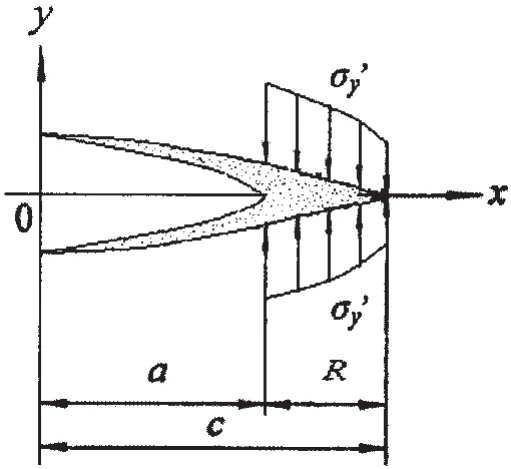
Fig.1 Dugdale model with damage
We can get the following expression of the damage β for a strain hardening material:

It is shown that the damage β in the plastic zone is a function of the strain hardening exponent n,the length of the plastic zone R,and the distance to the new tip of the crack x1=x-a.Dimensionless plastic zone size with damage theory can be solved from(as described by Ref.[10]for more details):
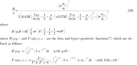
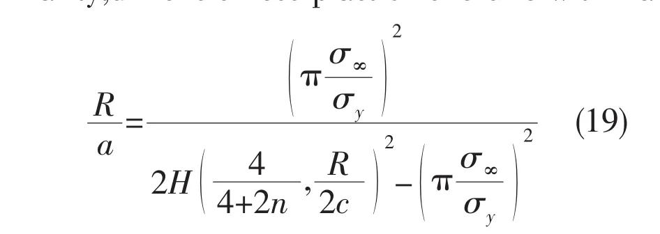
Similarity,dimensionless plastic zone size with fracture mechanics theory can be calculated by:
Dimensionless plastic zone size solution from Rice’s formula is expressed as:

The dimensionless plastic zones for strain hardening materials are calculated by Rice’s formula(Eq.(20)),fracture mechanics theory formula(Eq.(19))and damage formula(Eq.(18)),respectively,for the case of three strain hardening exponents,n=0.1,0.2,0.5.The results are shown in Fig.2.Note that the results calculated by damage formula are consistent well with those by fracture mechanics formula.However,without consideration of the damage effect on stress ratio and hardening exponent,the re-sults from damage formula are comparatively smaller than those of Rice’s.Hence,the formula of dimensionless plastic zone size with damage modification similar to Rice’s can be calculated by:
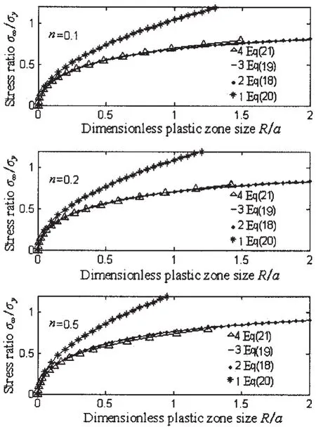
Fig.2 Comparison of dimensionless plastic zone size

From Fig.2,it can be seen that Rice’s modified solution with damage(Eq.(21))is consistent well with the damage solution(Eq.(18)).
For the case of small scale yielding,as described by Ref.[12],correcting for the strain hardening exponent from the view of energy,the modified strain hardening exponent n0is obtained without damage of material.Based on modified plastic zone size model with damage,as above discussed,Eq.(21),and correction method of strain hardening exponent in Ref.[12],plastic zone size R modified solution with damage of material can be calculated by:

In the case of small scale yielding,damage plastic zone size can be solved by a correction factor(as described by Ref.[10]for more details):

As above discussed,a general form for the extent of the plastic zone size can be written in the following form

A static tension test[13]was performed on specimens for 2024-T4(σy=301MPa,n=0.2)and 7075-T6(σy=465MPa,n=0.113)aluminum alloys.Characteristics of the stable hysteresis loop and fatigue life are shown in Fig.3.As shown in Fig.3.1 and 3.2,the correlation coefficients of the solutions from Eq.(23)and experiment values are 99.9%,99.9%,respectively.And the results show that the correlation coefficients of Ref.[13]prediction values and real values are 99.6%,98.1%.It can be seen that the calculated values from Eq.(23)by our proposed model provide a better approximation of experimental values than Ref.[13].
The approximate Eq.(22)can be verified by Ref.[14]data from the medium strength ferrite-pearlite steel(BM45)(with σy=335MPa and n=0.147)compact tension(CT)specimens with three different thicknesses:5.95mm,19.30mm and 24.20mm.The monotonic PZS on the surface of each CT specimen was measured by the fatigue in compression method.The mean value of α[see Eq.(25)]obtained from the experiments for the three thicknesses as equal to 0.188.The value,α,calculated by applying Eqs.(20),Refs.[12]and(22)are 0.278,0.225 and 0.164,respectively.Due to considering damage effect and modified strain hardening exponent nyof hardening material,the calculated values from Eq.(22)lie closer to the experimental results.
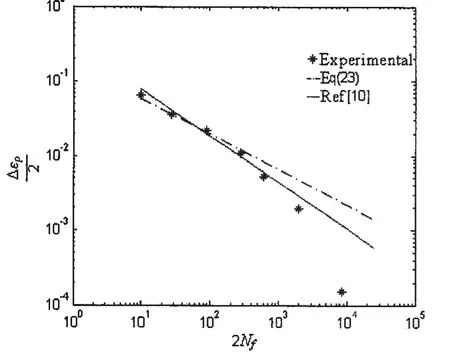
Fig.3.1 Relationship between fatigue life and plastic strain amplitude of 2024-T4 Al alloy
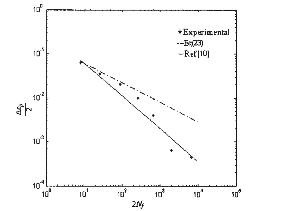
Fig.3.2 Relationship between fatigue life and plastic strain amplitude of 7075-T6 Al alloy
A 6.35mm thickness aluminum alloy(2024-T351)centre cracked plate specimen was cyclically loaded with R ratio of 1/10[14].The total maximum strain,ε,along the crack linemaxwas measured at Kmaxusing the moiré technique.For the numerical calculation,the cyclic yield strength,σy=460MPa,and the cyclic strain hardening exponent n=0.13,were used.The monotonic PZS ahead of crack tip values for Kmaxranging from 13.31MPam to 26.07MPa m are shown in Fig.4.The results indicate that the calculated values from plastic zone size R solution by our proposed model are closer than those from Ref.[14]without damage and Rice’s formula to the experimental results.

Fig.4 Maximum plastic zone size(PZS)at the crack tip for 6.35mm thick center flaw specimen at R=1/10.
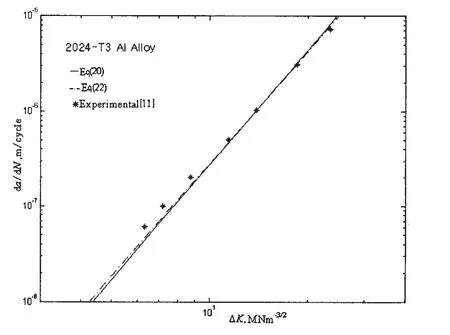
Fig.5 Comparison between experimental and computed curves of da/dN vs ΔK
Fig.5 shows the computed and observed crack growth rate with stress intensity factor range for 2024-T3(σy=303MPa,n=0.5)Al alloy sheet under cyclic tensile loading[15].The results indicate that the calculated values from Eq.(22)by our proposed model are closer than and Rice’s formula Eq.(20)to the experimental results.
3 The relationship between AE activities and plastic zone at crack tip
During fatigue crack propagation,deformation and fracture within plastic zone are the major sources of AE activities.Assuming that AE count is proportional to the volume of plastic zone,it can be written as

Under fatigue loading,assuming increment in plastic zone length is equal to the crack extension increment,in one fatigue cycle,

Eq.(27)bears strong similarity with the equation relating AE counts to stress intensity factor and plastic zone size[16-21],a similar power law Paris relation for AE rate,namely,dη/dn=A( ΔK )m.Combined with Eq.(13),a power relationship exists between crack growth rate and AE counts per loading cycle with stress intensity(or plastic zone size),which providing damage mechanics basis and physical background for AE investigation during fatigue.
4 Calculation results and comparison with test data
Test results demonstrated that acoustic emission is occurring phenomenon during material deformation,cracking and propagation process,and thus sensitive to damage process.And material will present different AE characteristics under various external stresses.A damage parameter D was defined as the ratio of total ring down counts η at a given instant to the sum of ring down counts occurring until failure ηf,D=η/ηf,damage variable β during AE is characterized as follows:

The stress intensity factor is given by[22]

Fig.6 shows AE counts rate,the theoretical and experimental AE counts as a function of the number of cycles(data from Ref.[22]).As shown in the figure,the calculated results by our proposed model provide a better approximation of experimental values than Ref.[22].

Integrating Eq.(30)(η from η→ηf,N from N→Nf,Nfis failure lifetime)and the function of the total AE counts η with cycles N is obtained by:

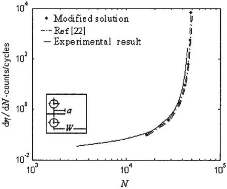
Fig.6 Comparison of theoretical and experimental results for intermittent proof tests
This equation has the similar form during high and low cycle fatigue for tests by AE method[23-24].Substituting Eq.(31)into Eq.(28),damage variable expression is described by

Eq.(32)has the same form as Eq.(8),the general expression of fatigue damage variable.The response of total AE counts ratio η/ηfand damage parameter β against cycle ratio[22]is plotted in Fig.7.It can be seen that with slight damage the total AE counts ratio curve can be turned into the damage evolution curve including damage evolution characteristics,and a big error for them with serious damage.
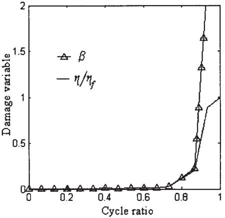
Fig.7 Damage variable evolution curve
5 Conclusions
Based on damage mechanics,damage characteristics during fatigue and acoustic emission(AE)activities are studied.According to the damage evolution equation,a power relationship exists between crack growth rate and AE counts per loading cycle with stress intensity(or plastic zone size),namely,Paris’formula form,which providing damage mechanics basis for AE monitoring.Accounting for damage effect on the size of plastic zone,a modified model for the plastic zone with damage is presented,including the gradual deterioration of materials due to the formation and propagation of micro-defects.It shows that the results of our proposed model are in a good agreement with experiments.Considered AE parameter as damage variable,damage expression during AE activities is developed.By analyzing available experimental data,the proposed model’s predictions are more consistent with the test data.And the damage evolution expression is consistent with the experimental results.
[1]Mukhopadhyaya C K,Jayakumara T,Raja Baldev.The influence of notch on the acoustic emission generated during tensile testing of nuclear grade AISI type 304 stainless steel[J].Materials Science and Engineering,2000,A276:83-90.
[2]Cai H,Evans J T.Acoustic emission analysis of stable and unstable fracture in high strength aluminium alloys[J].Engng.Fract.Mech.,1992,42:589-600.
[3]Gong B,Bao R D,Qi H,et al.Acoustic emission study on plastic material with notch[J].Tech.Acoust,2006,25:30-34.(in Chinese)
[4]Robotnov Y N.Creep ruptures[C]//In:Applied Mechanics,Proceedings of the 12th International Congress of Applied Mechanics.(Edited by Hetenyi M,Vincenti W G)Standford-Springer-Verlag,Berlin,1969:342-349.
[5]Lemaitre J.Formulation and identification of damage kinetic constitutive equations[M].Continuum Damage Mechanics Theory and Applications,(Edited by Krajcinovic D,Lemaitre J)NewYork:Springer Verlag,1987:37-89.
[6]Dugdale D S.Yielding of steel sheets containing slits[J].J Mech.Phys.Sol.,1960,8:100-104.
[7]Luo A,Mou Y,Han R P S.A large anisotropic damage theory based on an incremental complementary energy equivalence model[J].Int.J Fract.,1995,70:19-34.
[8]Davidson D L,lankford J,JR.Plastic strain distribution at the tips of propagating the cracks[J].Transactions of the ASME,1976,1:24-29.
[9]Rice J R.Stress due to a sharp notch in a work-hardening elastic-plastic material loaded by longitudinal shear[J].J appl.Mech.Trans.ASME,1967,34:287-298.
[10]Wang H J,Lin Z.Modification of plastic zone damage model and the effect to the Acoustic Emission Activities[J].J Ship Mech.,2011,15:389-393.(in Chinese)
[11]Mathematic Dictionary Editorial Commission.Mathematic Dictionary[K].Nanjing:Dongnan University Press,2002.(in Chinese)
[12]Kujawski D,Ellyin F.One the size of plastic zone ahead of crack tip[J].Engng.Fract.Mech.,1986,25:229-236.
[13]Huang J H,Si Y,Zheng L G,Dong X H.A dislocation model of low-cycle fatigue damage and derivation of the Coffin-Manson equation[J].Materials Letters,1992,15:212-216.
[14]Guerra-Rosa L,Moura Branco C,Radon J C.Monotonic and cyclic crack tip plasticity[J].Int.J Fatigue,1984,6:17-24.
[15]Elber W.The significance of fatigue crack closure[J].ASTM STP,1971,486:230-242.
[16]Lee K L.Cyclic AE count rate and crack growth rate under low cycle fatigue fracture loading[J].Engng.Fract.Mech.,1989,34:1069-1073.
[17]Lindeley T C,Palmer I G,Richards C E.Acoustic emission monitoring of fatigue crack growth[J].Materials Science and Engineering,1978,32:1-15.
[18]Sinclair A C E,Connors D C.Acoustic emission analysis during fatigue crack growth in steel[J].Materials Science and Engineering,1977,28:263-273.
[19]Bassim M N.Detection of fatigue crack propagation with acoustic emission monitoring of fatigue crack growth[J].Non Destructive Testing and Evaluation International,1992,25:287-289.
[20]Gong Z,Nyborg E O,Oommen G.Acoustic emission monitoring of steel railroad bridges[J].Materials Evaluation,July 1992:883-887.
[21]Roberts T M,Talebzadeh M.Acoustic emission monitoring of fatigue crack propagation[J].J Constructional Steel Research,2003,59:695-712.
[22]Wang Z M.Fundamentals of Acoustic Emission[M].Shandong:Shandong Science Technological Publishing House,1990.(in Chinese)
[23]Bassim M N,Houssny-Eman M.Acoustic emission during the low cycle fatigue of AISI 4340 steel[J].Materials Science and Engineering,1984,68:79-83.
[24]Houssny-Eman M,Bassim M N.Study of the effect of heat treatment on low cycle fatigue in AISI 4340 steel by acoustic emission[J].Materials Science and Engineering 1983,61:79-88.
声发射技术对材料疲劳过程的损伤特征的研究
王慧晶,林 哲
(大连理工大学 船舶工程学院,辽宁 大连 116024)
文章考虑损伤效应,研究材料疲劳过程损伤特征及相对应的声发射活动性。导出的疲劳损伤演化方程具有与声发射活动相似的Paris公式形式,发展了研究裂纹声发射活动的损伤力学方法。又通过分析损伤对塑性区尺寸的影响,提出塑性区损伤修正模型。采用该修正模型的预测结果与实验结果基本吻合。并以声发射参数为损伤变量提出声发射活动中的损伤发展规律。经试验数据分析,文中提出的塑性区修正模型可以较好地反映声发射活动规律,损伤发展规律符合试验观察结果。
声发射;损伤;塑性区;应变硬化
TG115.28
A
王慧晶(1978-),女,大连理工大学船舶工程学院博士生;
林 哲(1957-),男,副教授。
TG115.28
A
1007-7294(2011)12-1394-11
date:2011-01-17
猜你喜欢
杂志排行
船舶力学的其它文章
- Numerical Research on Ventilated Supercavity Shape and Flow Structure in the Turning Motion
- A Comparative Investigation on Optimization of Propeller Blade Section Design
- Experimental Investigation of Sloshing Loads and Structural Dynamic Responses in Tanks of LNG Carriers
- Comparative Analysis of Vortex Induced Nonlinear Vibration of Casing Pipe under Three Different Boundary Conditions
- Nonlinear Model for Vibration Analysis of Fluid-conveying Pipes via the Incremental Harmonic Balance Method
- Coupled Vibration of Fluid-filled Functionally Graded Material Cylindrical Shell
