A Meshless Numerical Approach for Stress-Assited Corrosion on Ship Body
2011-06-07
(School of Naval Architecture and Civil Engineering,Zhejiang Ocean University,Zhoushan 316004,China)
A Meshless Numerical Approach for Stress-Assited Corrosion on Ship Body
TANG Zhi-bo
(School of Naval Architecture and Civil Engineering,Zhejiang Ocean University,Zhoushan 316004,China)
The evolution of a crack-like defect that propagates by stress driven corrosion on ship body,with assumption of an isotropic,linear elastic solid,is simulated by applying Meshless Local Petrov-Galerkin(MLPG)method,where the simplest MLPG5 method has been adopted.Comparing with former simulation results,it is found that,when handling crack related numerical simulation,MLPG method is much more convenient than conventional finite element method.Depending on material properties,loading,and temperature,the three possible behaviors for the flaw are observed:gross blunting,stable,and unstable sharpening of the crack tip,respectively.
corrosion;MLPG;stress-assisted;static fatigue
Biography:TANG Zhi-bo(1971-),male,Ph.D.,professor of Zhejiang Ocean University.
1 Introduction
Advanced fiber reinforced composites and optical glasses are widely exploited in the design of ship building industries.The durability of the materials in service is therefore a major concern.Experiments suggest that the lifetimes of many components are limited by subcritical crack growth(Zhou and Curtin,1995)[1].Under sustained loading conditions,two classes of crack growth are observed,depending on the stress,temperature and material.At elevated temperatures,the most common form of failure is by crack growth along interfaces or grain boundaries.In contrast,at room temperature,or in a corrosive environment,transgranular fracture is the dominant mechanism of failure.In amorphous materials such as glass,transgranular subcritical crack growth is the main mode of failure at all temperatures.The focus of this paper is subcritical transgranular crack growth in brittle elastic solids.
In general,reinforced composites are notable for their resistance to a hostile environment.Nevertheless,if a stressed component is exposed to chemical attack,it may suffer from a form of delayed fracture known as static fatigue(Hillig and Charles,1965;Michalske,1983)[2-3].This behavior has been attributed to a process involving chemical dissolution of material from the region near the tips of small pre-existing cracks in the solid(Wiederhorn,1975)[4].The loss of material causes cracks to progressively sharpen and increase in length until catastrophic fracture occurs.Experiments have revealed that,for a given material and ambient environment,the time to failure is a strong function of the applied stress.In particular,if the applied stress lies below a threshold value,known as the fatigue limit or stress corrosion limit,failure can be avoided.It is clearly desirable to determine this limit,and in situations where the stress must exceed the corrosion limit,to determine the rate of crack growth as a function of the applied stress.In the literature,the latter is often expressed empirically as υ=AKnor υ=Bexp C( )K from the experimental data(Freiman et al,1985;Wiederhorn et al,1974)[5-6].The main objective of the present work is to present a physics-based model to describe the subcritical crack growth behavior within a grain or in amorphous media.
Charles and Hillig(Charles and Hillig,1962)[7]were the first to develop a micromechanical model of crack growth by corrosion.They considered the behavior of an elliptical cavity in an isotropic,linear elastic solid,using a model based on absolute reaction-rate theory to characterize the rate of dissolution of material from the crack flanks(Hillig and Charles,1965)[2].The essential feature of this model is that the rate of material loss from a surface is influenced by both the stress acting tangent to the surface and also by surface curvature.Stress generally tends to increase the rate of material loss,while the curvature of a concave surface reduces it.The competition between these two effects may be characterized by a dimensionless parameter

where σtipis some measure of the stress near the cavity tip,γ is the free energy per unit area of the unstressed surface,and ktipis the surface curvature near the crack tip.For large Σ,the effects of stress dominate over curvature,so that the ellipse tip propagates more rapidly than the flanks.This causes the ellipse to sharpen,and eventually results in the formation of a crack which triggers brittle fracture.For small Σ,the effects of stress are negligible.Material at the tip of the ellipse then dissolves more slowly than material near the flanks,and the ellipse is blunted,eventually evolving to a rounded cavity.The critical value of Σ that discriminates between blunting and sharpening gives the static fatigue limit for the solid.Charles and Hillig estimated the critical Σ by assuming that the crack remains elliptical throughout its evolution.
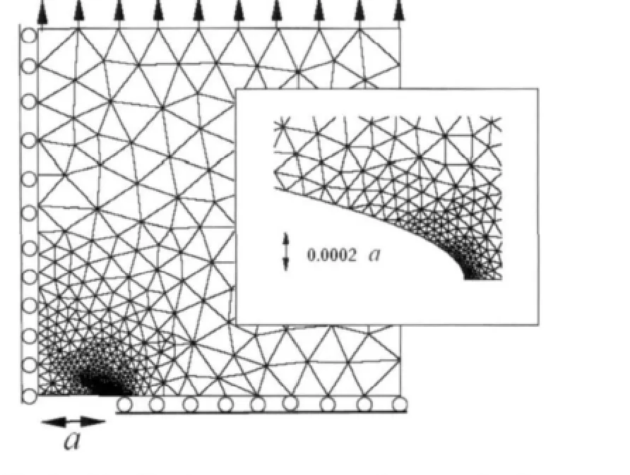
Fig.1 Idealized geometry used to study the growth of a stress corrosion crack in an elastic solid,showing a typical node distribution and meshes for integration domains.The crack is elliptical,with ratio of semi-axes b/a=0.01.Each mesh shown is a triangle,so that each integration domain for every node in MLPG5 includes some triangles,and one Gauss integration point is applied on every triangle,since the test function is constant.
Existing micromechanical model is based on a simple geometrical description of the crack.In this paper,we use a numerical technique to compute in detail the evolution of a crack propagating by stress driven corrosion.We consider a large,plane,linear elastic solid which contains a crack-like notch near its center.We adopt Hillig and Charles’(1962)[7]constitutive law to describe the rate of material loss from the crack surface as a function of stress and curvature.The MLPG5(Atluri and Shen 2002;Tang et al,2003)[8-9]method is used to solve the coupled equations of linear elasticity and those governing material loss from the crack surface,which is a typical time-dependent problem.
Our results confirm many of the predictions of existing models:we observe a transition from crack blunting to sharpening at a critical value of Σ;we find that m(a dimensionless material parameter)has a strong influence on the behavior of the crack.However,some surprising insights emerge from our simulations.In particular,we find that the transition from blunting to sharpening is determined not only by the driving force for material removal,but also by the kinetics of this process,so that there is no single pair of values for Σ and m which lead to crack sharpening.Instead,the critical combination of Σ and m depends on a third dimensionless material parameter Φ,which is a function of temperature.The implication of this result is that the fatigue threshold for a given material is likely to vary with temperature.Secondly,our results show that the initial rate of material loss from the crack surface is not a good predictor of its subsequent behavior.Consequently we observe three types of crack growth:(i)Gross blunting;(ii)Stable,quasi-steady state notch like crack growth;and(iii)Sharpening,accompanied by the formation of a neck near the crack tip.We find that regime(i)will occur in all materials,provided that the applied load is sufficiently low.In contrast,regime(ii)exists only in materials in which m exceeds a critical threshold.In such materials,the crack will blunt at low loads,or sharpen to propagate as a self-similar notch at higher loads.The crack would presumably continue to grow in this manner until the stress near the crack tip exceeds the ideal strength of the solid.In materials with m below the critical threshold,the ellipse appears to sharpen without limit,and rapidly forms an ideal crack.
2 Model description
We idealize a typical component as a planar,isotropic,linear elastic solid with Young’s modulus E and Poisson’s ratio v,Fig.1.The solid is assumed to contain a single crack like flaw,with characteristic length 2a,near its center.In this paper,we will report results only for an initially elliptical cavity,but we have obtained similar results for a notch-like flaw with constant tip curvature and at sides.The solid is loaded by a uniform remote stress σ∞acting perpendicular to the major axis of the flaw,thereby inducing a displacement field uixj()and stress distribution σijxj()within the solid.The displacement and stress fields are related by the usual linear elastic constitutive law and the stress must satisfy the equilibrium equations σij,j=0.In subsequent discussions,we will assume that the displacements uiare small,implying that the change in shape of the cavity surface due to elastic distorsion of the solid is negligible.We will,however,account rigorously for large changes in shape of the reference configuration as material is dissolved near the crack tip.

The defect surface is assumed to be exposed to an unspecified,chemically reactive species,which progressively removes material from the solid.We use Hillig and Charles’constitutive law to characterize the resulting rate of loss of material.In developing this model,it is assumed that chemical reactions at the solid/vapor interface limit the rate of material removal,so that it is not necessary to account explicitly for processes involving diffusion of material to or away from the reaction site,nor is it necessary to model adsorption or desorption of chemically reactive species at the surface.The reaction is driven by a difference in chemical potential between the material near the solid surface and the reaction product,and the rate of reaction is determined by a combination of the driving force and the activation energy associated with the chemical process.In the absence of stress,this causes a flat surface to recede at uniform rate υ0,which is generally a function of temperature.Surface curvature and stress modify the chemical potential of atoms near the void surface,and also influence the activation energy.The recession rate of a curved,stressed surface is therefore expressed as

here,υnis the normal velocity of the surface in the unstressed reference configuration(υnis negative because the surface is receding),R is the gas constant and T is temperature.In addition,

where σ=σijtitjis the tangential stress at the solid surface;Vmis the molar volume of the solid;α is a dimensionless phenomenological constant such that αVm=∂φ/∂()σσ=0is the activation volume for the reaction;β is a second dimensionless constant,which accounts for both a quadratic term in stress in the Taylor expansion of the activation energy about σ=0 and also for the strain energy released as atoms are removed from the surface;E′=E/1-v2( )is the plane strain modulus;γ is the energy per unit area of a stress free surface and k is the surface curvature,defined so that k>0 for a concave surface.Additional details concerning the derivation of this kinetic law may be found in Hillig and Charles(Charles and Hillig,1962)[7].
3 Numerical procedure
We have used MLPG5 and one-dimensional finite element method to solve the equations outlined in the preceding section.It is convenient to divide the calculation into three steps.Assume that the shape of the crack or notch at time t=0 is known.The first step is then to de-termine the distribution of stress in the solid at time t=0.Next,we determine the material lost from the void surface during a subsequent interval of time Δt.Finally,the reference configuration is updated,and a new distribution of stress is computed for time t=Δt.The computation is repeated to determine the evolution of the crack as a function of time.
The MLPG5 method for linear elastic solids is used to compute the distribution of stress in the solid,where the test function is the Heaviside step function(constant over each local sub-domain),and trial function is linear,and it is based on a local symmetric weak-form(Atluri and Shen,2002)[8].We also use a finite element procedure to calculate the change in shape of the void surface as material is removed by corrosion,which could be regarded as a one-dimensional problem.Let Δh()s denote the depth of material lost during a time interval Δt at position s on the void surface.From the preceding section,we have

Due to the presence of surface curvature in the expression for φ,it is difficult to integrate this equation with respect to time using an explicit Euler scheme.We therefore use a semiimplicit method,noting that the change in curvature of the surface during a time interval Δt may be estimated as

We use this estimate in a general Euler time integration scheme

where 0≤θ≤1 is a parameter controlling the time integration.For θ=0,Eq.(7)reduces to a standard explicit forward-Euler scheme,while choosing θ=1 corresponds to a semi-implicit scheme with a first order predictor for curvature.Choosing θ>0 has a marked impact on the stability of the algorithm,allowing time step sizes to be increased by several orders of magnitude without loss of accuracy.Our tests show that θ=1 leads to the best numerical stability,while the best accuracy appears to occur around θ=1.The accuracy is relatively insensitive to θ,however,since small time steps must be taken to ensure that the stress field is updated correctly.We have used θ=1 in all the computations reported here.Combining Eqs.(6)and(7)and writing the result in weak form then leads to
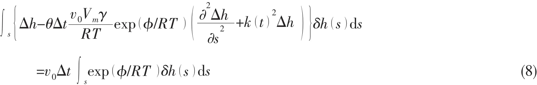
here,δh(s ) is a twice continuously differentiable test function of arc length around the void surface,and S denotes the void surface.Eq.(8)must be satisfied for all admissible δh(s).The usual finite element procedure is used to obtain a discrete form of Eq.(8):the variations of δh(s)and Δh(s ) are interpolated between discrete points on the void surface by means of piecewise cubic Hermitian interpolation functions,which allows the surface integrals to be expressed in terms of a finite set of values of Δh,δh and ∂h/∂s,∂δh/∂s.The condition that Eq.(8)must hold for all δh then leads to a sparse,unsymmetric,system of linear equations to be solved for the discrete values of Δh and ∂Δh/∂s.
These results then form the basis for a finite element solution for the shape of the corrosion crack as a function of time.At time t=0,the initial shape of the crack is specified by a set of‘control points’ on the void surface.The geometry of the solid is then interpolated between these points,using cubic parametric splines.The analysis begins by generating “nodes”for meshless method to fill the solid.We have found that the advancing front method of Peraire et al(Peraire et al,1987)[10]is particularly effective for this purpose.The algorithm allows one to generate optimal distribution of node density at each time step:denser at crack tip and coarser at other regions.A typical node distribution map is illustrated in Fig.2:the map contains approximately 3 000 nodes.The shortest distance between nodes near the crack tip is of approximately 10-6a,where a is the crack length.For a crack length of 10μm,this corresponds to a spacing between nodes of only 0.01nm.
We then proceed to compute a stress field and estimate the values of nodes that lie on the void surface,which are then used to generate a one-dimesional finite element mesh to solve Eq.(8).Finally,nodal values of Δh and ∂Δh/∂s on this “mesh” are used to compute a new spline representation for the void surface.The procedure is repeated to determine the history of crack propagation.
4 Results and discussion
To discriminate between the various regimes of behavior of the crack,we adopt the following dimensionless measures of stress,material properties and crack geometry
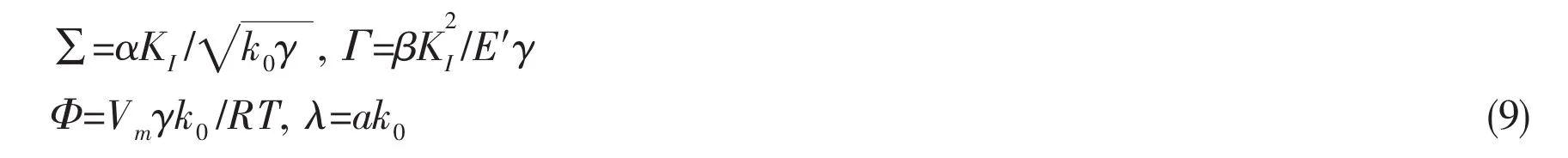
here,KI=σis the crack tip stress intensity factor,k0is the initial crack tip curvature,γ is the surface energy,E′is the plane strain modulus,Vmis the molar volume of the solid,R is the gas constant and T is temperature.Finally,α and β are the two dimensionless parameters appearing in the corrosion law(3-4).Note that one may also define an additional(but not independent)dimensionless parameter

which is a function only of the material properties and is independent of applied loading.In addition,we introduce the dimensionless time measure

Provided that the conditions necessary for the applicability of linear elastic fracture mechanics are met,the values of λ and Φ,together with any two of the parameters Σ, Γ or m,completely characterize the behavior of the crack.It is straightforward to appreciate their physical significance:Σ quantifies the relative effects of crack tip curvature and crack tip stress on the rate of material removal by corrosion:for large Σ,stress dominates,tending to cause rapid crack growth,while for small Σ crack growth is retarded by the influence of curvature.Similarly,Γ,can be loosely thought of as the ratio of crack tip energy release rate g=/E′to the Griffiths toughness gc=2γ.Large positive values of Γ imply a large driving force for crack growth.However,because the chemical reaction at the crack tip may either provide an additional thermodynamic driving force for crack growth,or may involve additional energy dissipation as heat,the condition g=gcneed not be satisfied for the crack to advance,and crack growth is possible for all values of Γ.Indeed,since the kinetic parameter β may be negative,for some materials it is possible that Γ<0.The dimensionless parameter Φ describes the kinetics of crack growth:a large value for Φ implies a large change in crack tip velocity with stress or curvature.Finally,the material parameter m quantifies the relative magnitudes of the linear and quadratic terms in the driving force for stress driven material removal.For m<0,the linear term tends to increase the rate of crack growth with stress,while the quadratic term retards growth.For m=0,the linear term has no contribution,reducing the corrosion law to the form used by Wilkins and Dutton(Wilkins and Dutton,1976)[11].For m>0,both linear and quadratic terms in the expansion tend increase the rate of crack growth,and in the limit m→∞the linear term in the corrosion law dominates.
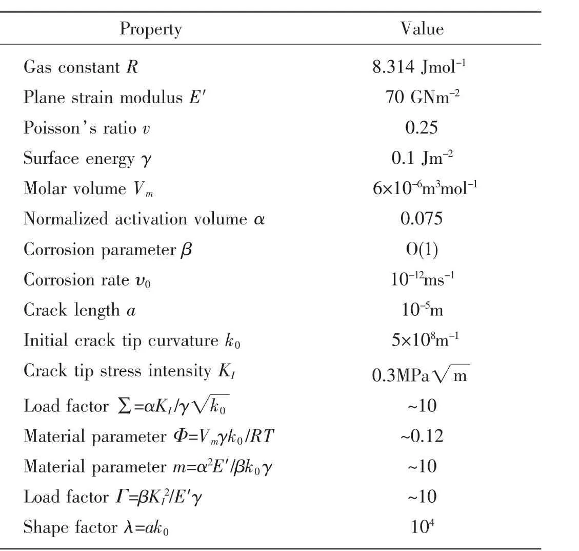
Tab.1 Representative values for material properties
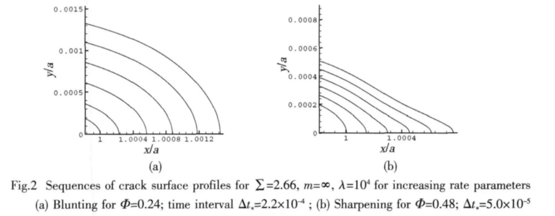
Typical values for the material parameters in our model are listed in Tab.1.We now proceed to investigate the behavior of the crack for the range of physically reasonable values of the dimensionless parameters.For simplicity,we will consider first the case Γ=0 m→()∞ ,wherein the linear term in stress in the expression for the driving force for crack growth dominates over the quadratic term.We observe the behavior of the crack in one two possible regimes:(i)Gross blunting;(ii)stable,quasi-steady notch like crack growth.The typical surface profiles near crack tip,corresponding to regimes above,are presented in Fig.2.
We turn next to examine the influence of kinetics on crack growth behavior.We pick identical values of remote stress Σ and material parameter m=0,but two different values of Φ.Since Φ influences the relative magnitudes of the crack’s surface velocity at its tip and flanks,in this case,we have noticed that,increasing Φ has a qualitatively similar effect to increasing Σ.For low values of Φ,the crack always blunts;while for high values of Φ the crack tip sharpens.An important consequence of this observation is that the critical value of Σ required to trigger crack sharpening depends on Φ.Since Φ is temperature dependent,our simulations suggest that the fatigue threshold will vary with temperature.Lower temperatures increase Φ and therefore decrease the fatigue threshold.
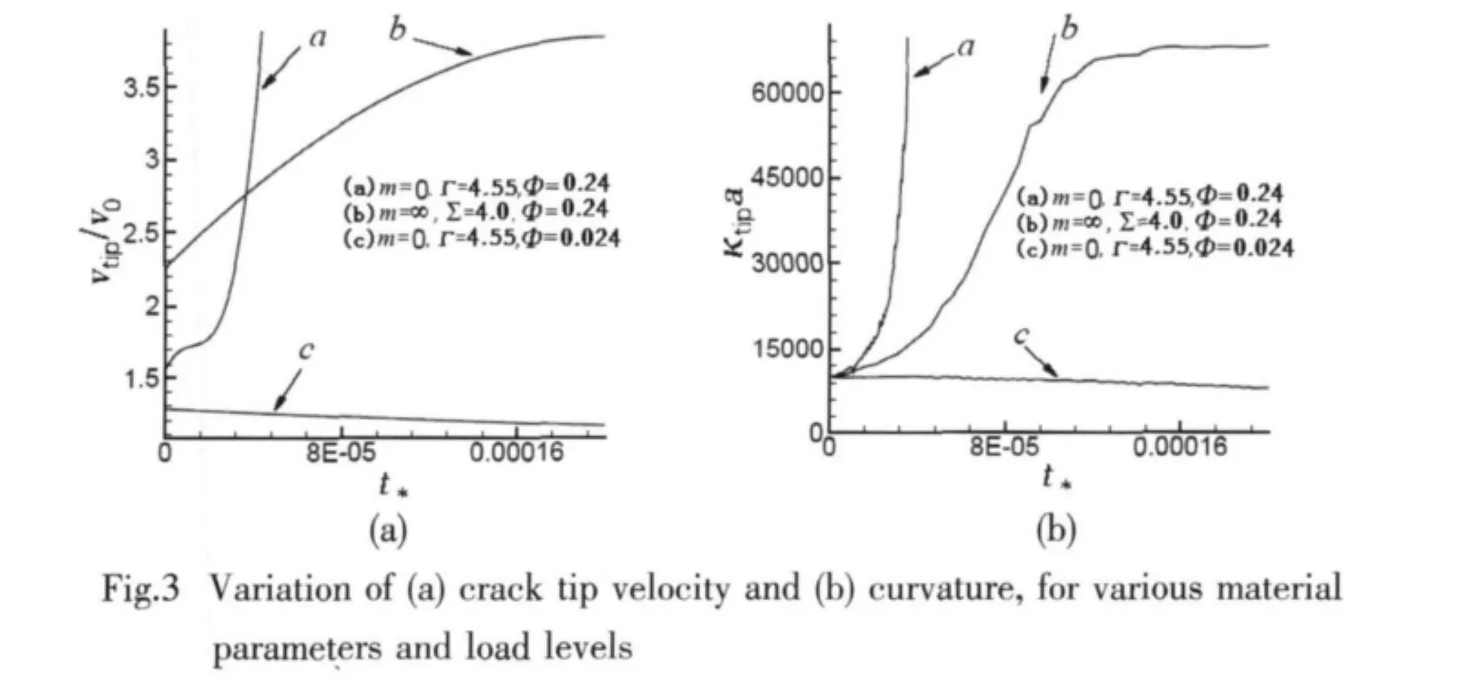
We have also investigated the role of the material parameter m in governing crack growth behavior.As an example,we next present results for m=0,wherein the quadratic term in stress in Eq.(4)dominates over the linear term.For this case the load level must be parameterized by the dimensionless group Γ,since Σ =0 for all stress levels.The behavior of the crack is different with the results presented for m=∞.For low loads,the crack blunts,while for high loads,the crack sharpens.However,in this case a sharpening crack never stabilizes:instead,the crack tip curvature and velocity both increase to the limit of the resolution of our finite element method.Evidence for this assertion is presented in Fig.3,which shows variations of crack tip curvature and velocity for various combinations of material parameters and applied load levels.For m=0,both the crack tip curvature and velocity appear to increase without limit if the load Γ exceeds the fatigue threshold.
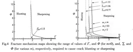
We have conducted many further simulations to investigate the thresholds in cases either Σ &Φ or Γ&Φ dominating the driving force.The results are arranged in Fig.4.As for m=∞,we note that the fatigue threshold is generally a function of Φ,and consequently is a function of temperature.
Finally,in the regime of stable notch-like crack growth,the variation of crack tip velocity with applied load is of particular interest.Dimensional considerations indicate that the steady state crack tip velocity and curvature may be expressed as
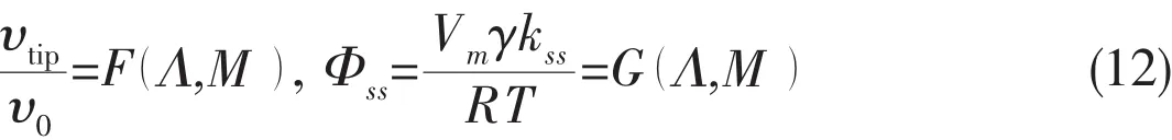
where G and F are functions to be determined,kssdenotes the steady-state crack tip curvature,and
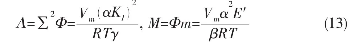
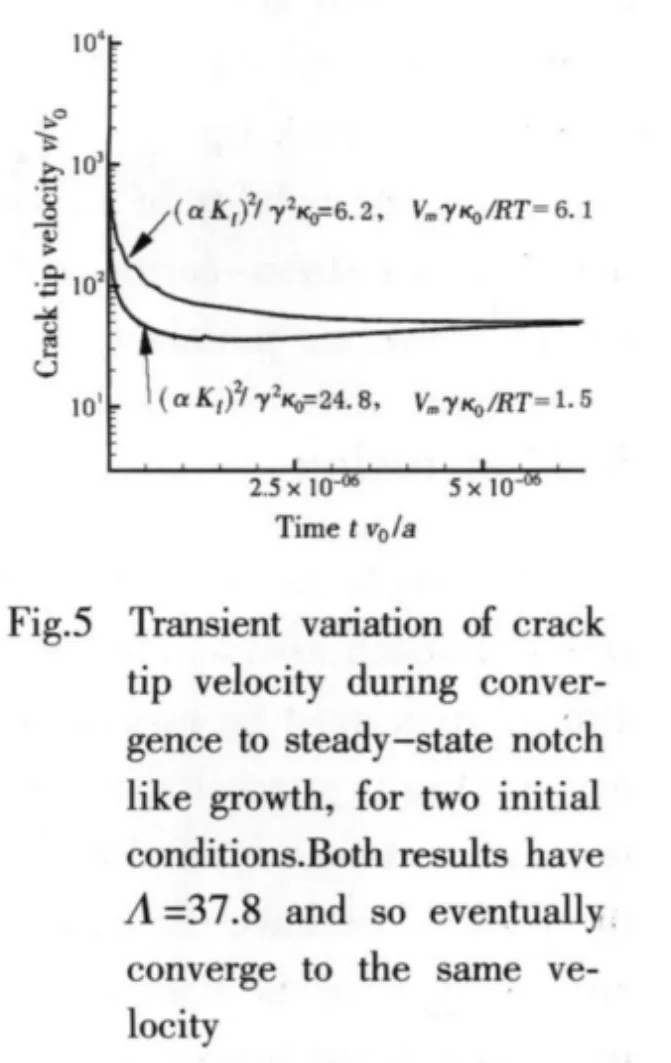
Fig.6 illustrates this trend.The figure shows the variation of crack tip velocity with time,for two cracks with identical values of crack driving force Λ=37.8,but different initial conditions(Σ=2.48;Φ=6.1)and(Σ=4.98;Φ=1.5),respectively.In both cases m=n=∞ and λ=104.After an short transient period,both cracks propagate with the same crack tip velocity,regardless of the initial conditions.
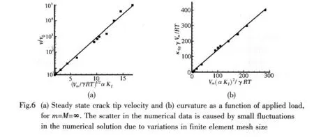
We have calculated the steady state crack tip velocity and curvature as functions of load parameter Λ,for the particular case m=n=∞.Results are shown in Fig.6,and suggest that our numerical data may be approximated by a crack tip velocity law of the form

This is in remarkable qualitative agreement with experimental observations,which are generally fit by υ=Bexp( C KI),where B and C are empirical constants that depend on temperature and nature of the corrosive environment(Wiederhorn,1975;Wiederhorn et al,1974)[4,6].Quantitative agreement is less satisfactory,however.Experiments indicate that B~10-21ms-1and C~90(M P a)-1(Wiederhorn et al,1974)[6],while data listed in Tab.1 suggest that B~10-21and C~90(M P a)-1.This discrepancy may be partly due to errors in values for material properties listed in the table:our predictions are particularly sensitive to variations in γ and α.There are several other explanations,however.Using data in Tab.1,our calculations predict steady state crack tip curvatures of the order 1011m-1,and the crack tip stress is correspondingly high.The validity of a continuum linear elastic solution in this regime is questionable.In addition,our stress-corrosion law is somewhat speculative,and requires experimental verification.These are promising areas for future study.
5 Conclusion
A simple meshless approach has been applied in simulating the crack evolution with stress-assisted assumption.Our simulations confirm the existence of a critical level of applied stress which must be exceeded to cause crack growth.Contrary to earlier predictions,however,our results suggest that the fatigue threshold is determined not only by the driving force for crack extension but also by the kinetics associated with the chemical reaction at the crack tip.Finally,we have used our computations to calculate the crack tip velocity as a function of applied load,in the regime of steady state notch like crack growth.Our results are illustrated in Fig.6,and are in excellent qualitative agreement with the standard empirical crack growth law υ=Bexp( C KI).Our calculations appear to underestimate values of C and overestimate B,however.This may partly be due to inaccuracies in values used for material data,but may also be due to the limitations of a linear elastic continuum analysis.
Acknowledgement
This work is supported by ZJNSF under award No.Y507197,and Education Department under award No.20061137.Author also thanks his former advisor,Dr.Allan Bower,Brown University,for his generous help.
[1]Zhou S J,Curtin W A.Failure of fiber composites:A lattice Green function model[J].Acta Metall.Mater,1995,43(8):3093-3104.
[2]Hillig W B,Charles R J.Surfaces,stress-dependent surface reactions and strength[M].In High Strength Materials.Zackaray V F.Wiley&Sons,New York,1965:682-705.
[3]Michalske T A.The stress corrosion limit:Its measurement and im-plications[M].In Fracture Mechanics of Ceramics.ed.Bradt R C,Evans A G,Hasselman D P H,Lange F F.Plenum Press,New York,1983,5:277-289.
[4]Wiederhorn S M.Crack growth as an interpretation of static fatigue[J].J Non-Cryst.Solids,1975,19(1):169-181.
[5]Freiman S W,White G S,Fuller E R,Jr.Environmentally enhanced crack growth in soda-lime glass[J].J Am.Ceram.Soc.,1985,68(3):108-112.
[6]Wiederhorn S M,Evans A G,Fuller E R,Johnson H.Application of fracture mechanics to space-shuttle windows[J].J Am.Ceram.Soc.,1974,57:319-323.
[7]Charles R J,Hillig W B.The kinetics of glass failure by stress corrosion[C]//In Symposium on Mechanical Strength of Glass and Ways of Improving it,Union Scientifique Continentale du Verre.Charleroi,Belgium,1962:511-527.
[8]Atluri S N,Shen S.The meshless local Petrov-Galerkin(MLPG)method[M].Tech.Science Press,2002.
[9]Tang Z,Shen S,Atluri S N.Analysis of materials with strain-gradient effects:A meshless local Petrov-Galerkin(MLPG)approach,with nodal displacements only[J].CMES,2003,4(1):177-196.
[10]Peraire J,Vahdati M,Morgan K,Zienkiewicz O C.Adaptive remeshing for compressible flow computations[J].J Comp.Phys.,1987,72:449-466.
[11]Wilkins B J S,Dutton R.Static fatigue limit with particular reference to glass[J].J Am.Ceram.Soc.,1976,59(3-4):108-112.
船体表面应力腐蚀问题的一种无网格计算方法研究
唐志波
(浙江海洋学院 船舶与建筑工程学院,浙江 舟山 316004)
文章采用无网格方法(MLPG)中最简单的MLPG5技术,对船舶表面微裂缝在腐蚀工作环境中向内扩展情形进行了数值计算模拟,计算中假设了船体材料为各向同性,并引入了线弹性假设。对比以往的有限元计算方法,发现处理裂缝扩展的数值计算问题时,无网格计算方法显示了其独特的优越性。同时,根据材料特性、外荷载以及温度等参数的变化,文中分别描述了三种可能的裂缝扩展方式:裂缝钝化、稳态以及非稳态的快速破环等。
腐蚀;MLPG;应力腐蚀耦合;静态疲劳
U662.2
A
唐志波(1971-),男,博士,浙江海洋学院船舶与建筑工程学院教授。
U662.2
A
1007-7294(2011)06-0649-11
date:2011-04-30
Supported by ZJNSF under award No.Y507197,and Education Department under award No.20061137
猜你喜欢
杂志排行
船舶力学的其它文章
- Evaluation of Surface Crack Shape Evolution Using the Improved Fatigue Crack Growth Rate Model
- On Implementing a Practical Algorithm to Generate Fatigue Loading History or Spectrum from Short Time Measurement
- Vibration of Cracked Plates under Tensile or Compressive Load
- Local Wave Applied to Detect and Characterize Acoustic Emission Signals
- Application of Wavelet Denoising in the Modeling of Ship Manoeuvring Motion
- CFD Simulation of the Unsteady Performance of Contra-Rotating Propellers