正交铺设陶瓷基复合材料基体裂纹演化研究
2011-04-19杨福树孙志刚李龙彪宋迎东
杨福树 孙志刚 李龙彪 宋迎东
(南京航空航天大学能源与动力学院,南京,210016,中国)
INTRODUCTION
Ceramic matrix composites are one of the most promising candidates for aero components as they show many attractive properties over traditionalceramics: higher tensile and flexural strength,enhanced fracture toughness and impact resistance,lower density and no or less cooling requirements[1-3].
Knowledge of matrix crack evolution is very important for the development of fiber reinforced ceramic matrix composites[4].In particular,it is necessary to study the sequence of such microscopic damages up to the final fractures to ensure the damage tolerance capability.Zok and Spearing[5-6]calculated the strain energy release rates for matrix crack growth with interference from neighboring crack slip zones in unidirectional ceramic composites.Curtin[7]presented a theory to describe the evolution of multiple cracking in brittle matrix composites.A full statistical treatment ofthe matrix crack evolution and associated stress-strain behaviors in unidirectional ceramic composites has been developed[8].However,the damage evolution in cross-ply laminates is more complex as the matrix cracks occur in both 0°and 90°plies.Kuo[9]classified the damage modes of a cross-ply ceramic composite into five types(as shown in Fig.1),and theoretically derived the cracking stress of each mode by the energy balance approach.However,it did not consider the interaction between different modes[10]. Daniel et al.[11]observed and predicted the type and sequence of failure mechanisms and their interaction by the micro-mechanics of brittle matrix single layers and the macro-mechanics of a cross-ply laminate.Takeda[12]investigated the matrix crack evolution in SiC fiber-reinforced glass-matrix cross-ply laminates both experimentally and theoretically from a micro-mechanical viewpoint.
Although cross-ply laminates are most important in practical applications of ceramic matrix composites,the microscopic damage evolution has not been well characterized yet.The purpose of this paper is to characterize the matrix crack evolution of cross-ply ceramic matrix composites under uniaxial tensile loading theoretically from a micro-mechanical viewpoint.The effects of ply thickness,fiber volume fraction,interface shear stress and interface debonding energy on cracking stress and matrix crack evolution are discussed.

Fig.1 Classification of damage states in brittle matrix cross-ply laminates
1 ENERGY BALANCE CRITERION FORMATRIXCRACK EVOLUTION
The observed damages are classified into 13 patterns,considering the neighboring damage modes.Each damage pattern can be divided into one or more repeated elements.For one crack in each repeated element,ΔU is defined as a function of debonding length Ls,crack spacing s,and applied stressec.

where W is the work done by an external load and Uallis the sum of energy terms.

where Ucis the crack surface energy,Udbthe interface debonding energy,and Usthe energy loss due to interface friction.Ufand Umare the strain energies in fibers and matrix in 0°plies,respectively.U2is strain energy in 90°plies.The energy terms in Eq.(3)are written as


where b and d are the half thickness of 0°and 90° plies,respectively.Ef,Em,and E2the Young′s modulus of fiber,matrix,and 90°ply,respectively.
From the energy balance with each repeated unit before and after a damage growth,the critical stress for such damage growth can be determined using the following formula
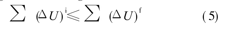
where superscripts i and f denote before and after the damage growth,respectively.The summation is made over all cracks in the repeated unit.
2 MATRIX CRACK EVOLUTION PATTERNS
According to the experiments for SiC/CAS cross-ply composites tested under tensile loading, transverse cracks were observed to appear first in 90°ply[13].As the transverse crack density increases with the loading to a critical level,the matrix cracks bridged by fiber appear in 0°plies. With further investigation on SiC/CAS cross-ply composite[10],it is found that the initial cracking stress of mode 3 is the lowest among the four matrix cracking models,the following one is mode 5.Based on these results,mode 3 and mode 5 damages occur between existing mode 1 damages are investigated in this part.
2.1 Pattern 1:mode 3 damage occurs between existing mode 1 damages
2.1.1 Stress analysis and debonding length prediction
By consideration the equilibrium condition with the external load,the axial stresses satisfy (b+ d)ec=bVfef(x)+ bVmem(x)+ det(x)(6) where ecdenotes a remote uniform external load worked on composite;ef(x),em(x),and et(x) denote the fiber,matrix stress in the 0°ply,and stress in the 90°ply,respectively;Vf,Vm(=1-Vf)the volume fraction of fiber and matrix in the 0°ply composite.
Fig.2 shows the matrix crack evolution of pattern 1.In the case,the mode 3 damage appears between transverse cracks. Taking the symmetry of the stresses into consideration,it is only to focus on the stresse distribution in half crack spacing s.And the stresses before the mode 3 crack appears are given by[10]

where x is the distance from the crack plane,as shown in Fig.2.The superscripts of estand for the damage state.The shear-lag constant λis derived in Ref.[10].

Fig.2 Schematic representation of pattern 1
When the mode 3 damage appears(as shown in Fig.2),it is assumed that the stress in the 90° ply has no effect on the stress in the 0°ply,and the stress in the 90°ply can be found as

In debonded regions,the relationship between the interface shear stress fiand the axial stress in a fiberefis given by

where rois the fiber radius.In the case,it is assumed that the interface shear stress is a constant in the debonded region.And the boundary conditions at the crack plane are

Combined Eqs.(6,8-10),the axial stress of the fiber in the interface debonded region is obtained as

The axial stress of the matrix in the debonded region is obtained as

The stresses distribution in the bonded regions(x>Ls)are found as

For x≥Ls,the fiber/matrix interface ceases to slide,and the stresses approach those of the no damage state(mode 0).From the stress equilibrium of a fiber

the interface debonding length can be found as

2.1.2 Cracking stress for pattern 1
Taking the symmetry of the stresses in the crack spacing 2s into consideration,it is just necessary to focus on the energy changes ranging from x=0 to x=s.Before the mode 3 damage appears,the surface energy Uc=0,Udb=0,Us=0. Substituting Eq.(7)into Eqs.(2,4),other energy terms can be obtained.
As the mode 3 damage appears,the crack surface energy Uc=0.5bVmVm+ 0.5dVt,and the interface debonding energy Udb=2 bVfLs/ro,where VmandVtare the surface energy per unit area in the 0°ply and 90°ply,respectively.Substituting Eqs.(8,11-13)into Eqs.(2,4),other energy terms ranging from x=0 to x=s can also be obtained.Combining Eq.(15)and Eq.(5),the cracking stress can be found.
2.2 Pattern 2:mode 5 damage occurs between existing mode 1 damages
2.2.1 Stress analysis and debonding length prediction
Fig.3 shows the mode 5 damage occurrs between transverse cracks.In this case,it is assumed that the stress in 90°ply is the same as the stress in mode 0,that is

Boundary condition at the crack plane is

Combined Eqs.(6,9,16,17),the axial stress of the fiber in the debonded region can be found as

In the debonded regions,the axial stress of the matrix is

In the bonded zone(x>Ls),the stresses distribution are

In the bonded zone,the fiber/matrix interface ceases to slide,and the stresses approach those of the mode 0.From the stress equilibrium of a fiber

the interface debonded length is given as


Fig.3 Schematic representation of pattern 2
2.2.2 Cracking stress for pattern 2
For matrix crack evolution of pattern 2,the energy terms before the mode 5 damage occurrs are the same as those calculated in pattern 1.And it is just necessary to focus on the condition as the mode 5damage occurs.Here the crack surface energy Uc=0.5 bVmVm,the interface debonding energy Udb= 2 bVfLs/ro.Substituting Eqs.(16,18-20) into Eq.(4),other energy changes ranging from x=0 to x=s can be obtained.Combining Eqs. (5,22),the cracking stress is determined.
2.3 Numerical results
Numerical results for the prediction of critical stresses for the matrix cracking are obtained for matrix crack evolution of pattern 1 and pattern 2.The calculations are performed based on the material properties of the SiC/CAS composite listed in Table 1.In order to simplify the calculation,the effect of the thermal residual stress is not considered.
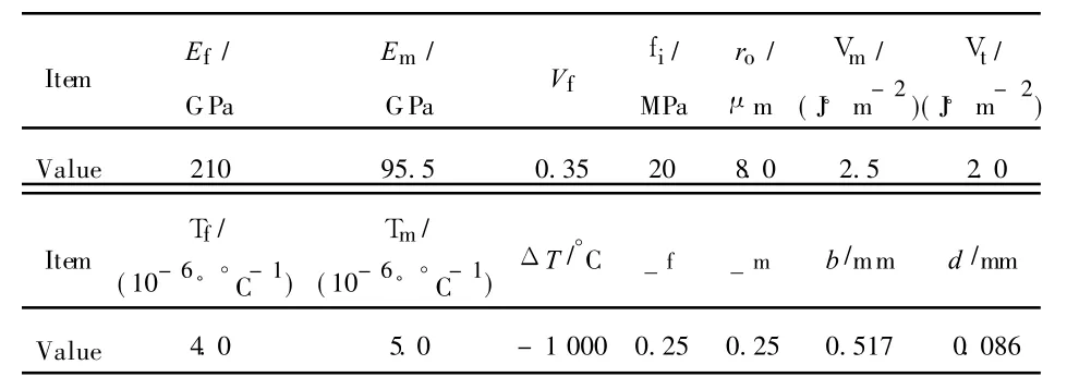
Table 1 Material properities of SiC/CAS ceramic composites[10]
2.3.1 Effect of ply thickness

Fig.4 Relationship of crack spacing and stress changing with ply thickness(b=0.517 mm)
The effect of ply thickness on critical stress of pattern 1 and pattern 2 is show n in Fig.4.As the 90°ply thickness approaches zero(Fig.4(a)), the solutions of the two patterns converge to one line,which coincide with the predicted critical stress for the unidirectional composites.As the 90°ply thickness increases,Figs.4(a,b)show that mode 3 damage is more likely to appear first between existing mode 1 damages compared with the mode 5 damage.The result is well explained by two aspects.On the one hand,the mode 5 damage appears in a lower matrix crack spacing than the mode 3 damage.It implies that the lower the crack spacing is,the more energy it will be cost.On the other hand,an increase in transverse ply thickness results in a decrease cracking stress of mode 3.While an increase in transverse ply thickness leads to an increase of cracking stress in mode 5.The reason lies in that there is no crack in 90°ply in mode 5.So the 90°ply can share more loads.
2.3.2 Effect of fiber volume fraction
Fig.5 shows the effect of fiber volume fraction on critical stress for crack evolution pattern 1 and pattern 2.Both mode 3 and mode 5 cracking stress increase as the fiber volume fraction increases.But the mode 5 cracking stress grows more quickly than the mode 3 cracking stress.In other words,it is the mode 3 damage that may occur first between existing mode 1 damages as the fiber volume fraction increases.
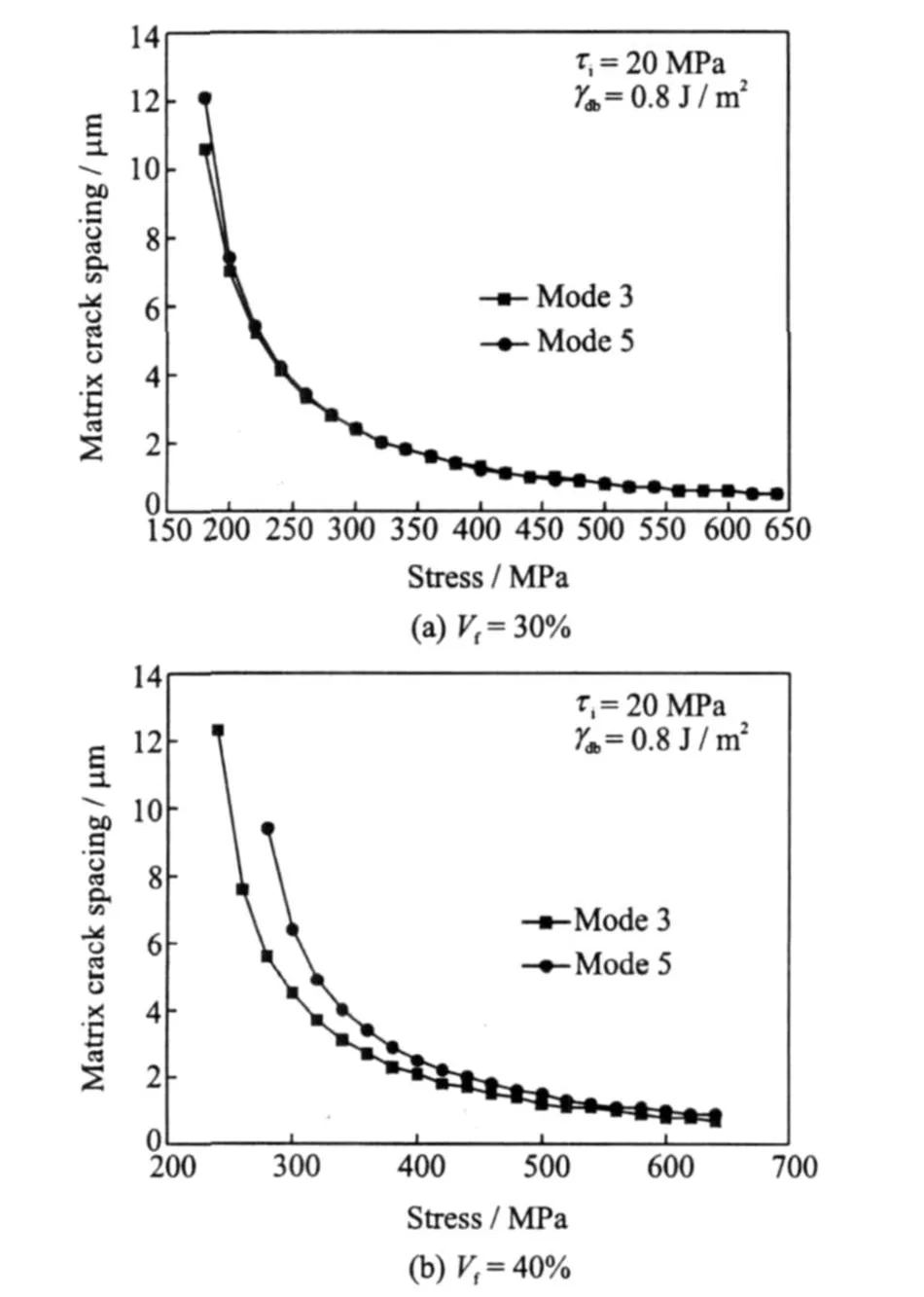
Fig.5 Relationship of crack spacing and stress changing with fiber volume fraction
3 MULTIPLE CRACK EVOLUTION OF MODE 3
From the results above,it is obvious that the mode 3 damage is more likely to occur between existing mode 1 damages than the mode 5 damage.So in this part,multiple crack evolution of mode 3 is investigated.Fig.6 shows this kind of crack evolution pattern.In order to distinguish the difference of interface debonding length before and afterthe mode 3 crack appears,Lsand Lndenote the interface debonding length before and after the new crack appears,respectively.

Fig.6 Schematic of multiple crack evolution configuration
3.1 Stress analysis
Similar to the stress analysis of patterns 1 and 2,it is just necessary to focus on the stresses in the section ranging from x=0 to x=s.Before the mode 3damage appears the stress distribution is given by Eqs.(8,11-13),where the coordinate x is shown in Fig.6(a).
When the new damage(mode 3)appears,it is found that the stress distribution ranging from x=0 to x=s is symmetrical.And the stresses are given by Eqs.(8,11-13).x varies from 0 to s/2. Here,the coordinate x is shown in Fig.6(b).
3.2 Cracking stress for multiple matrix crack evolution of mode 3
In the half crack spacing s,the surface energy Uc= 0,and the interface debonding energy Udb=2bVfLs/ro.Substituting Eqs.(8,11-13)into Eq.(4),other energy terms before the new crack appears can be found.As the mode 3 crack appears, the surface energy Uc= 0.5 bVmVm+ 0.5dVt,and the interface debonding energy Udb= 2 bVfLs/ro.Substituting the corresponding stress-es into Eqs.(2,4),other energy terms can be obtained.Combining Eqs.(5,15),the cracking stress can be determined.
3.3 Numerical results
Take the[03/90/03]-SiC/CAS for example. In order to simplify the calculation,the effect of the thermal residual stress is not considered.
3.3.1 Effect of interface shear stress on matrix crack spacing
Fig.7 shows the effect of interface shear stress on matrix crack spacing.It shows that the matrix crack spacing decreases with the increase of interface shear stress at the same stress level. The reason is that the loads work at the fiber/matrix interfacial area increase as the interface shear stress increases,so the matrix should bear more loads.According to the critical matrix strain energy criterion[14],the crack spacing will decrease as the matrix strain energy reaches the critical value.

Fig.7 Matrix crack spacing and stress at different interface shear stress
3.3.2 Effect of interface debonding energy on matrix crack spacing
As is shown in Fig.8,the matrix crack spacing decreases with the increase ofinterface debonding energy at the same stress level.The reason is that an increase of energy dissipation is required as the interface debonding energy increases.It results in the decrease of the debonding length. The decrease ofinterface debonding length leads to an increase of load acted on the matrix,causing the decrease of the matrix crack spacing as the matrix strain energy reaches the critical value.

Fig.8 Matrix crack spacing and stress at different interface debonding energy
3.3.3 Effect of ply thickness on matrix crack spacing
Fig.9 shows the effect of ply thickness on matrix crack spacing.It shows that the matrix crack spacing increases with the increase of 90° ply thickness,here b=0.517 mm.The reason is that if the external load is given,there is an decrease of loads acted on the matrix as the 90°ply thickness increases.This leads to an increase of crack spacing as the matrix strain energy reaches the critical value.

Fig.9 Matrix crack spacing and stress at different ply thickness(b=0.517 mm)
3.3.4 Effect of fiber volume fraction on matrix crack spacing
As is shown in Fig.10,the matrix cracking spacing decreases with the increase of fiber volume fraction at the same stress level.The reason is that the area of the matrix decreases as the fiber volume fraction increases.In other words, there will be an increase of the stress of the matrix when the external load is given.It will lead to an decrease of crack spacing as the matrix strain energy reaches the critical value.

Fig.10 Matrix crack spacing and stress at different fiber volume fraction
4 CONCLUSIONS
(1)Matrix crack evolution of cross-ply ceramic matrix composites under uniaxial tensile loading is investigated by micro-mechanics approach.
(2)The crack mode 3 and mode 5 appearing between transverse cracks is investigated.It is found that the mode 3 is more likely to appear.
(3)The matrix crack evolution of mode 3 is investigated.It is found that the matrix crack spacing decreases with the increase of interface shear stress,interface debonding energy and fiber volume fraction,while the matrix crack spacing increases with the increase of transverse ply thickness.
[1] Li Longbiao,Song Yingdong,Sun Zhigang.Uniaxial tensile behavior of cross-ply ceramic matrix composites[J].Acta Materiae Compositae Sinica,2011, 28(1):1-8.(in Chinese)
[2] Li Longbiao,Song Yingdong,Sun Zhigang.Uniaxial tensile behavior of unidirectional fiber reinforced ceramic matrix composites[J].Acta Material Compositae Sinica,2008,25(4):154-160.(in Chinese)
[3] Fantozzi G,Reynaud P.Mechanical hysteresis in ceramic matrix composites[J].Materials Science and Engineering,2009(521/522):18-23.
[4] Marshall D B,Evans A G.Failure mechanisms in ceramic-fiber/ceramic-matrix composites[J].Journal of the American Ceramic Society,1985,68(5):231-255.
[5] Zok F W,Spearing S M.Matrix crack spacing in brittle matrix composites[J].Acta Metallurgica et Materialia,1992,40(8):2033-2034.
[6] Spearing S M,Zok F W.Stochastic aspects of matrix cracking in brittle matrix composites[J].Journal of Engineering Materials and Technology,1993,115 (3):314-318.
[7] Curtin W A.Multiple matrix cracking in brittle matrix composites[J].Acta Metallurgica et Materialia, 1993,41(5):1369-1377.
[8] Ahn B K,Curtin W A.Strain and hysteresis by stochastic matrix cracking in ceramic matrix composites[J]. Journal of theMechanics and Physics Solids,1997,45(2):177-209.
[9] Kuo W S.Damage of multi-directionally reinforced ceramic-matrix composites[D].Newark: DepartmentofMechanicalEngineering, University of Delaware,1992.
[10]Kuo W S,Chou T W.Multiple cracking of unidirectional and cross-ply ceramic matrix composites[J]. Journal of the American Ceramic Society,1995,78 (3):745-755.
[11]Daniel I M,Anastassopoulos G.Failure mechanisms and damage evolution in cross-ply ceramic-matrix composites[J].International Journal of Solids and Structures,1995,32(3/4):341-355.
[12]Takeda N,Kiriyama M.Matrix crack evolution in SiC fiber/glass matrix cross-ply laminates[J].Composites Part A:Applied Science and Manufacturing, 1999,30(4):593-597.
[13]KarandikarP,Chou T W.Characterization and modeling of micro-cracking the elastic moduli changes in Nicalon-CAS composites[J].Composites Science and Technology,1993,46(3):253-264.
[14]Robertson D D,Solti J P,Mall S.Modeling of matrix failure in ceramic matrix composites[J].Journal of Composites Technology and Research,1997,19 (1):29-40.
