地震作用下的剪力墙结构分析
2011-03-19孟庆利赵文军
丁 琳,孟庆利,洪 岩,赵文军,孙 静
(1.黑龙江大学,哈尔滨 150080;2.哈尔滨工业大学,哈尔滨 150001;3.中国地震局工程力学研究所,哈尔滨 150080)
Ⅰ Introduction
The test shows vibration machines for the structure.Datas in this test which it were used for subsequent analysis of silo building by using software DINAX[1].As the test was carried out with empty structure,the analysis assumed that silo was empty.The analysis has showns that the upper silo gallery can play a role of passive vibration damper under some conditions it affects on the structure positively.
This analysis shows a simplified model of structure with four lumped masses[2].It is supposed that this model is the most appropriate for an analysis of such kind of buildings.But because this model actually is simplified model there're some doubts about a correctness of results[3].
To perform deeper non-linear analysis of the silo building was using in modem engineering software as SAP2000[4].
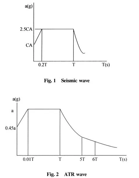
Also recently the design codes were revised with increasing of seismic force and check existing building in accordance these code[5-6].The follow-ing pictures are the seismic wave of code and ATR wave(picture 1 and picture 2)。
Recently the design codes of many countries were revised with increasing of seismic force and it will be better to check existing building in accordance with the codes[7].SAP2000 were chosen because of its popularity in the world and availability in the study[8].It has shown a subsequent study of the software which a powerful and reliable tool for designing and can calculate almost all types of building[9].
First a model of silo building for SAP2000 was created;then different loads were assigned.Before calculation in order to bring into sync,the analytic model with real one is compared to the other models.

Ⅱ Analysis
Generally a silo building consists of three parts:
1.Under silo gallery.It is frame part of building,which support silo banks and is the most critical part of it.T he cross section of column is 1 000 mm×1 000 mm.Cross section of beams is 500 mm×600 mm.The height of first floor is 6 000 mm.
2.Shell thin-walled structures is used in silo banks.The thickness of the walls is 180 mm.The diameter of the banks is 6 000 mm.The clear height is 36 000 mm.
3.Upper silo gallery.It is used for setting some equipments for maintenance of building.The cross section of column is 300 mm×300 mm.The cross section of beam is 300 mm×300 mm.The height of upper silo gallery is 4 800 mm.
4.Also there are braces on the first floor and upper silo gallery.T he silo building as a fourth mass model and with an assumption of upper floor, under some conditions,it can play a role of a passive vibration damper.The masses were lumped in the first floor in the center of mass for silo banks on upper floor and on the ruff.In the first part of study it proves a correctness of the previous calculation.
Before calculation in order to bring into sync the analytic model with real one are compared to have these two models.The comparison is about correspondence of natural
Period ofreal model and computer,one showns that these two models correspond to each other quite well(table 1).

Table 1 Periods were the following
The periods are almost coincided.It proves the accuracy of computer model.The first calculation performed with the empty building to create two models.It's reasonable to set flexible upper floor and two braces at the corner of it in the first one and second set the fixed upper floor in the second one.It fixed upper silo gallery by installing additional shear walls.
The results hsow that actually it's right to assumpt the upper silo gallery plays a positive role in the experiment.Without fixing,the upper silo gallery affected on structure positively.
Plastic hinges in structure which put them in connection of columns on first floor with slab of silo banks is most critical part of the building.The grain wheat under earthquake action begins to act along the height of the structure,but in stable condition,this action is absent.There is only some pressure on the wall of banks.SAP2000 offers a possibility to assign lumped masses in any nodes of structure.These masses can be assigned in three directions independently.Thus it assigned lumped masses to horizontal directions in nodes along the height of the building and in three directions only on the first floor.Mass acting in vertical direction is mass of whole grain wheat in silo banks.The weight of grain wheat is 0.75 t by m3.T he building was filled up on two thirds.
The upper floor considered as passive vibration damper in the previous calculation,in the model with filled up banks it doesn't work.That means upper floor in reality doesn't have any influence on the behavior of the structure in case the structure is full.
From all these calculations several preliminary conclusions about performance of structure were made.
1.In case of empty structure,this paper proved a correctness of the calculation in previous analysis.The upper floor plays positive role in performance of the structure.
2.In case of full structure,as it is in reality, the upper floor doesn't contribute any significant changes in performance of the structure.
3.Plastic hinges introducing has shown very slight change in natural period of structure and in inner forces.It happens because the building entirely represents as structure with quite stiff body on flexible supports.The plastic hinges can appear only in place of connection between this rigid body and supports.And it can't introduce any significant dissipation of energy throughout the structure.But actually,even though the building represented as rigid body and flexible
A cross section of columns on first floor from obtained moments and shear forces are checked. The check had shown insufficiency of reinforcement in columns and an area of cross section of columns must be more developed.In order to improve the behavior of the structure under earthquake action,were some shear walls installed on the first floor.The thickness of shear walls was 200 mm. In comparison between building with ordinary braces and the building reinforced by installing shear walls.
A reduction of bending moment and shear force in the columns of structure are following table 2.

Table 2 Bending moment and shear force in the columns of structure
From this example,the shear walls installing on the first floor of the structure gives significant reduction of displacement,bending moment and shear force in the weakest point of it.
Introducing plastic hinges has slight change in natural period of the structure and inner forces. Because the building is entirely represents as structure with quite stiff body on flexible supports.The plastic hinges can appear only in place of connection between rigid structure and supports and it is hard to introduce any significant dissipation of energy throughout the structure,even though the building supports system study that plastic hinges should bring more noticeable changes.
Ⅲ Conclusion
1.Checking the cross section of columns shows an insufficiency of reinforcement and area of cross section in them.
2.The structure has not quite good design scheme and installing some shear walls on first floor to get reduction of stress in columns.It gives possibility to reduce cross section of column and increase common resistibility of structure against earthquake action.
3.the results of test for empty structure is not appropriate using this kind of structure.Installing some shear walls on the first floor can change the behaviors of the structure.
[1]Nie Jian-guo,Huang Yuan.The Non-linear Earthquake Responde M odel for Steel-concrete Beams[J].Journal ofTsinghua University(scienceand technology), 2009,49(3):329-332(in Chinese).
[2]Wilson E.L.Structure Analysis on Static and Dynamic [M].Beijing:China Building Industy Press,2006: 111-216(in Chinese).
[3]Wei Yong,Xian Jia-ru.Shear Wall Non-linear Analyses with SAP 2000[J].Journal of Tsinghua University (Science and Technology),2005,45(6):740-744 (in Chinese).
[4]Chopra A.K.Dynamics of Structure.Theory and Application to Earthquake engineering[M].Upper Saddle River,New Jersey:Prentice-Hall,Inc.,1995.
[5]T.Paulay and M.J.N.Priestley.Seismic Design Reinforced Concrete[M].Wiley-interscience,2001.
[6]Computer and Structure,Inc.SAP2000 Non-linear,Integrated Structural Analysis&Design Software[M]. California:Berkeley,1997.
[7]Wolf J.P.;Dynamic Soil Structure Interaction[M]. Upper Saddle River,New Jersey:Prentice Hall,1985.
[8]Chopra A.K.,"Dynamics of Structures-Theory and Applications to Earthquake Engineering"[M].Upper Saddle River,New Jersey:Pretince-Hall,Inc.,1995.
[9]Kramer S.,"Geotechnical Earthquake Engineering" [M].Upper Saddle River,New Jersey:Pretince-Hall, Inc.,1996.
