FITTING CORRECTION METHOD OF RING ARTIFACTS FOR RECONSTRUCTING CONE-BEAM CT IMAGES
2010-10-08LuoShouhuaWuJingZhangBoChenGong
Luo Shouhua,Wu Jing,Zhang Bo,Chen Gong
(1.School of Biological Science&Medical Engineering,Southeast University,Nanjing,210096,P.R.China;2.Information Engineering Department,Jiangsu Provincial Hospital of TCM,Nanjing,210029,P.R.China)
INTRODUCTION
Ring artifacts on cone-beam computed tomography(CBCT)images are introduced by the nonuniformity of the flat-panel detector element response,which always appear as rings with different radius centered on the rotational axis.It is common in the process of CT image reconstruction. The reasons for such unsatisfactory responses are as follows:pixel defects of the detector;pixel nonlinear response on various X-ray intensity;inconsistent responses among pixels on certain X-ray intensity;pixel nonlinear responses on various X-ray spectra;instability of dark-field and bright-field of thedetector,etc[1].Due to the reason that data of the constructed images are corrupted by these ring artifacts,qualitative and quantitative analyses of CBCT images will be compromised.
Presently,there are many methods to reduce ring artifacts,including hardware and software approaches. The hardware approach is mainly used to improve the system scan sampling procedures[2],thus pixels with inconsistent response can obtain different radial signals,and then all inconsistencies of the detector systematic response will be uniformly distributed over whole sampling sequences on the initial projection and acquisition stages,resulting in effective reductions of ring artifacts.The software approach includes filtering and correcting methods.The filtering method is a post-processing technique in the image reconstruction.Aimed at the characteristics of ring artifact on the CT image,the researchers make a number of target filters,which can filter out artifacts and reserve the high-frequency edges of the images at the same time[3-5].However,these filters increase the reconstruction timeand result in blurs and degradation of the reconstruction images.The correcting method can overcome these two shortcomings by preprocessing the projective images.Different correcting methods depend on different factors of ring artifacts[6-7].Theclassical correcting methods only deal with the offset errors,and such kind of correction does not completely suppress the inconsistency of the pixel re-sponse.This paper uses the fitting correction method to suppress the ring artifacts of theimage reconstruction,which makes the curves of different pixels response to the radial intensity and suppress the ring artifacts.Finally,how to improve the fitting correction is discussed.
1 MATERIALSAND METHODS
1.1 Ring artifact f ormation
As an example,for simplicity,two-dimensional parallel beam projection is introduced.As shown in Fig.1,sot coordinate system is presented by the xoy coordinate system with rotatingθ angle around theorigin o.One-dimensional detector is located inside s axis and parallel-beam rays parallel to t axis.θis the angleof the ray-detector system rotating around body;f(x,y)the point on the projected plane and f(r,h)the corresponding point in polar coordinates against the xoy coordinate system.

Fig.1 Geometric diagram of ring artifact caused by inconsistency of channel response
According to the geometric relationship,the projection position of f(x,y)located on s axis is

The ray-detector system rotates a circle around the rotation axis,that is,the angleθincreases from 0°to 360°.If r is invariable and h keeps synchronous increase withθ,the value of s will be constant.That is,the projection location of all points on the round circle with thecenter at the origin and the radius r on projection plane is the sameon thedetector.If responses of different pixels are inconsistent,the data of every round circle will not alter smoothly,and ring artifacts occur.
1.2 Methods
Before correcting projection images,the response curve of the pixel to the X-ray intensity of Hamamatsu C7921CA-02 detector is shown in Fig.2.

Fig.2 Pixel curves of responses vs.tube current(photon flux)
As seen in Fig.2,the response curve of the pixel to the intensity ray is nearly linear.However,the slope and the intercept of curves vary in corresponding response curves which make the response inconsistent among pixels.If all response curves tend to be the average one,as shown in Fig.2(b),the response inconsistency can be suppressed.

where i is the current output intensity of the X-ray source;Gi(x,y)the output gray value of the pixel(x,y).a(x,y)and b(x,y)are the slope and the intercept of the response curve of pixel(x,y);andthe slope and the intercept of all pixel average response curve,respectively,thus

In the fitting process,the current variable i would not be allowed because of different dimensionalities with the image gray value.Through Eqs.(2-3),the current variables can be eliminated.
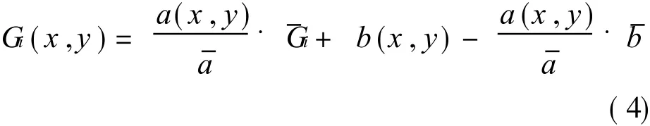
Assuming that
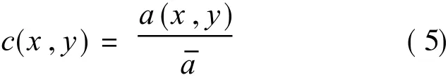

Eq.(4)is simplified as

where c(x,y)and d(x,y)are the correction factors that need to be solved with the fitting correction method.Through Eq.(7),correction factors of each pixel can be solved by fitting a straight line.The details of whole procedure are as follows:capture n pieces of idle load pictures which are exposed by X-ray with same voltage strength and different currentintensities.Theaverageoutput gray scale of each picture is set as x-coordinate. And y-coordinate represents the output gray scale value of each pixel(x,y)exposed by different current intensities. And then, the straight lineis fitted across these points by a least square algorithm.As a result,the scope and the intercept of the line represent correction factors c(x,y)and d(x,y).Finally,the projected image is corrected through Eq.(8)
G′i(x,y)=(Gi(x,y)-d(x,y))/c(x,y) (8)where Gi(x,y)is the gray scale value of the uncorrected projected image and G′i(x,y)the gray scale value of the corrected projected image.
2 RESULTS OF RECONSTRUCTION IMAGE
The results of the reconstructed images by the fitting correction of the projected images in micro-CT are shown in Fig.3.

Fig.3 Reconstruction images of foam aluminum materials
In order to achieve a good suppressive effect,more details and improvements for thefitting correction method are discussed:
(1)The variability of the correction factors c(x,y)and d(x,y)is presented as follows:when the idle load pictures are obtained with the same current intensity and different current-voltages under the X-ray irradiation,the fitting correction results are shown in Fig.4 with different frame numbers of 1 and 16.Fig.4(a)shows the idle load picture taken in one frame,Fig.4(b)shows the idle load picture taken up to 16 frames.From the picture,the ring artifact removal efficiency of Fig.4(b)is better than that of Fig.4(a).This is because the ups and downs of ray photons will cause a certain degree of inconsistency,and taking the average of more frames can help to eliminate this inconsistency.While the frame count is up to a certain extent,the effect on the reconstruction does not promote any more.In this paper,16 frames of each angle should be enough to meet needs for removing the ring artifacts.

Fig.4 Comparison of fitting results with different idle load picture frames
(2)Conventionally,the correction factor of each pixel is statically treated,but actually,there will be some bias.On the same X-ray voltage(70 k V)and different current intensities(30μA and 45μA),we obtain the idle load pictures of 400 angles,which are performed by fitting correction reconstruction with the same correction factor.The partial enlarging pictures of the same slice are show n in Fig.5.In Fig.5,Fig.5(a)is the reconstruction result of 30μA current intensity;Fig.5(b)is the reconstruction result of 45μA current intensity.It is obvious that the ring artifact of Fig.5(b)is clearer than that of Fig.5(a).The result shows that the same correction factor does not produce thesame result exactly when the same pixel of detector is radiated by different X-ray intensities.The fitting lines of correction factors are nonlinear.How to obtain these specific nonlinear factors is another improvement aspect.Fig.5 shows reconstructed idle load images exposed in X-ray sources with samevoltagestrength and different current intensities.
(3)As correction factors are solved by fitting correction,more fitting points are better for the result,especially for fitting points nearby the ring artifact areas.

Fig.5 Partial enlarged pictures of same slice
3 CONCLUSION
This paper uses the fitting correction method to reduce the ring artifacts of micro-CT reconstruction images.The fitting correction preprocesses the projection images and makes the entire pixel response curve linear so as to suppress the ring artifacts on the reconstructed images.The results testify the effectiveness of the method.More improvement aspects of the fitting correction are discussed,such as the average of multiframeimages and increasing fitting points,etc.
In addition,this paper mainly deals with ring artifacts caused by inconsistencies of the pixel response.There are also many other factors leading to ring artifacts,such as nonlinear factors in fitting straight line for correction factors which can be targeted on theimplementation in the future.References:
[1] Li Junjiang,Hu Shaoxing,Li Baolei,et al.Ring artifact correction for industrial CT images[J].Journal of Beijing University of Aeronautics and Astronautics,2007,33(11):1378-1382.(in Chinese)
[2] Fu Jian,Lu Hongnian.Correcting method for ring
artifacts in fan-beam X-ray ICT[J].Optics and Preci-sion Engineering,2002,10(6):542-546.(in Chinese)
[3] Yang Chen,Ma Jianhua,Feng Qianjin,et al.Nonlocal prior Bayesian tomographic reconstruction[J].Math Imaging,2008,30(2):133-146.
[4] Yang Jun,Zhen Xin,Zhou Linghong,et al.Geometric correction for cone-beam CT reconstruction and artifacts reduction[C]//The 2nd International Conference on Bioinformatics and Biomedical Engineering.Shanghai,China:IEEE,2008:2386-2389.
[5] Sun Haining,Qiu Shaokun,Lou Shanshan,et al.A correction method for nonlinear artifacts in CT Imaging[C]//Proceedings of the26th Annual International Conference of the IEEE.San Francisco:IEEE,2004:1290-1293.
[6] Zhou Zhenggan,Teng Shenghua,Jiang Wei,et al.X-ray flat-panel-detector-based digital radiography and its image calibration[J].Journal of Beijing University of Aeronautics and Astronautics,2004,30(8):698-701.(in Chinese)
[7] Li Junjiang,Lu Hongnian,Li Baolei.Study on nonuniformity correction of X RII-CCD pixel channel response based on BP neural network[J].Optical Technique,2007,33(2):273-280.(in Chinese)
杂志排行

Transactions of Nanjing University of Aeronautics and Astronautics的其它文章
- IMAGING CHARACTERISTICSOF RAT MODELSOF PARKINSON DISEASE
- MOTOR CORTEX NETWORKSIN STROKE PATIENTS DURING RECOVERY WITH f MRI
- FLUORESCENCE SPECTRUM ANALYSISOF ETHER-WATER SOLUTION BASED ON GAUSSIAN DECOMPOSITION METHOD
- EFFECTIVE DETECTION DEPTH OF NEEDLE-LIKE OPTICAL PROBE
- PREPARATION AND CHARACTERIZATION OF WATERSOLUBLE NEAR-INFRARED EMITTING PbSQUANTUM DOTS
- HYBRID MULTI-OBJECTIVE GRADIENT ALGORITHM FOR INVERSE PLANNING OF IMRT