EXPERIMENT ON THE CHARACTERISTICS OF 3-D VORTEX RING BEHIND A FLEXIBLE OSCILLATING CAUDAL FIN*
2010-07-02WANGZhidong
WANG Zhi-dong
School of Naval Architecture and Ocean Engineering, Jiangsu University of Science and Technology, Zhenjiang 212003, China, E-mail: cywzd@sohu.com
LAO Yi-jia
Technology Research Economy Development Institute, Beijing 10081, China
LI Li-jun, CONG Wen-chao
School of Naval Architecture and Ocean Engineering, Jiangsu University of Science and Technology, Zhenjiang 212003, China
EXPERIMENT ON THE CHARACTERISTICS OF 3-D VORTEX RING BEHIND A FLEXIBLE OSCILLATING CAUDAL FIN*
WANG Zhi-dong
School of Naval Architecture and Ocean Engineering, Jiangsu University of Science and Technology, Zhenjiang 212003, China, E-mail: cywzd@sohu.com
LAO Yi-jia
Technology Research Economy Development Institute, Beijing 10081, China
LI Li-jun, CONG Wen-chao
School of Naval Architecture and Ocean Engineering, Jiangsu University of Science and Technology, Zhenjiang 212003, China
A test for the wake vortex of a flexible oscillating caudal fin is carried out with Digital Particle Image Velocimetry (DPIV), and the variation of vortex distance and the vorticity in the range of oscillating frequency from 0.704 Hz to 1.17 Hz are analyzed. It is found that with the increase of the oscillating frequency, the vortex distance decreases and the peak of the vorticity increases, When the Strouhal number is smaller than 0.49, a larger thrust component is obtained. The distribution of the velocity circulation and the vortex distance in the different spanwise section of the caudal fin are given, and then the dimension of the vortex ring is determined. The radius of the vortex ring is 79.3 mm and the average velocity circulation is 28152.9 mm2/s at the oscillating frequency of 0.835 Hz. The model of 3-D vortex ring chain of flexible oscillating caudal fin is constructed based on the information of wake vortex field. Finally, an effective analysis method is provided for establishing the relationship of oscillating parameters for the caudal fin and the wake structure and the intrinsic mechanism of efficient fish swimming is investigated.
Digital Particle Image Velocimetry (DPIV), flexible caudal fin, flow field, vortex ring
1. Introduction
Now experiments on the structure of flow field of an oscillating fin become a hot topic in studying bionic propulsive mechanism. The quantitative analysis on the structure of vorticity field with the Digital Particle Image Velocimetry (DPIV) is very important in revealing the inherent mechanism of fishswimming with high propulsive efficiency[1].
The Particle Image Velocimetry (PIV) has been used to measure the flow field, and the flow visualization has been employed to determine the time-average velocity and locate the wake vortex position and find its structure[2,3]. From the measurement of the vorticity field of pitching and heaving motion of rigid and flexible foil, it was found that the kinetic parameters had great effects on the structure of wake field[4-8]. The different structures of vortical field of oscillating fin was examined with the increase of flexibility of the fin[9], and the radius ofvortex ring and the distance of vortex pair were found to be dependent on the swimming speed and the chord length of the fin[10]. In order to investigate the locomotion mechanism of fish, many researchers have carried out the experiments of the total flow field of fish, including the structure morphology of wake vortex of scombrid at horizontal and vertical section[11], the flow separation on the fish surface, the developing and shedding process of leading edge vortex and wake vortex of eel swimming[12], the vortex structure and its strength of the pectoral fin of crucian carp and sunfish with low- and high-velocity swimming[13], the vortical field structure at upper and lower margin of pectoral fin of bluegill and stickleback[14], the velocity and vortical field due to C-start of crucian carp and yellow catfish[15,16]. It was shown that the locomotion and the deformation of fish body and caudal fin have the positive effect on the structure of flow field and maneuvering of fish. Owing to the difficulty in testing the swimming parameters of live fish, the effect of caudal fin oscillating parameters on the characteristics of field structure was rarely presented in previous work.
By adjusting the deformation, oscillating amplitude and frequency of caudal fin, fish can realize the optimal control of surrounding water and forms special wake vortex field, thus resulting in the maximum thrust and highest efficiency. An experiment on the wake vortex in different sections of flexible oscillating caudal fin with DPIV is carried out, and the effects of oscillating position and frequency of caudal fin on the vortex strength and vortex distance are analyzed. Based on the quantitative analysis of the geometric characteristics of vortical field, the model of 3-D vortex ring chain is constructed. A reliable means of research and analysis are provided for establishing the relationship of caudal oscillating parameters and wake field structure.

Fig.1 Model of caudal fin and experimental equipments
2. Experiment
The experiment was carried out in a cyclic water tank at Jiangsu University of Science and Technology. Its section size is 300 mm×400 mm. The irradiation mode of DPIV uses laser irradiating. Tracer particles are made of Al2O3.The pixel size of CCD camera is 2048×2048. Working sequence is controlled by synchronizer. The experimental equipments are shown in Fig.1, and experimental parameters are presented in Table 1.
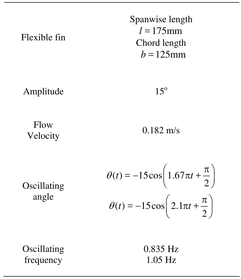
Table 1 Parameters of oscillating caudal fin
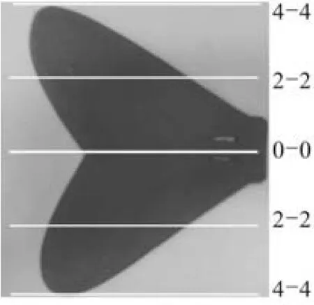
Fig. 2 Sections of caudal fin
The shape of the caudal fin is based on the measurement of the actual carp. The material of flexible caudal fin is rubber. The distance between upper edge of caudal fin and free surface is 85 mm. On account of symmetry of the caudal fin alongthe spanwise direction, three sections were selected for test, which are dorsal tip of caudal fin (4-4), spanwise midpoint (0-0) and midpoint of dorsal lobe (2-2), and they are shown in Fig.2. In each plane, three oscillating positions were selected to study their flow field, which are the equilibrium position, the left 13.5oabout the equilibrium position (see Fig.3) and the right 13.5oabout the equilibrium position (see Fig.4). The shooting of the position of the oscillating angle of caudal fin was controlled in real time by a PLC module and optical electric axial angle encoder, the arrows in the figures showing the direction of caudal fin oscillating.

Fig.3 Oscillating angle 13.5oleft about the equilibrium position
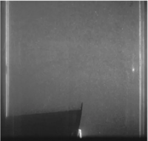
Fig.4 Oscillating angle 13.5oright about the equilibrium position
3. Results and discussion
3.1Flow field characteristics at different oscillating positions and sections of the fin
Because the caudal fin is asymmetrical in the spanwise direction, the characteristic of velocity field caused by oscillating motion of caudal fin is different in the 0-0 plane, 2-2 plane and 4-4 plane. Table 2 and Fig.5 present the average velocity in the flow field in these three planes at different oscillating positions and frequencies. Under the same oscillating frequency and position, the velocity away from the 0-0 plane exhibits the trend of declination. The results indicate that the average velocity of flow field is in inverse proportion to the oscillating frequency. That is, the increase of oscillating frequency causes the decrease of average velocity. In addition, the velocity gradient at the different oscillating positions has great difference, and there is little change of velocity along the spanwise direction when the oscillating angle of caudal fin is on the left 13.5oabout the equilibrium position.

Fig.5 Average velocity at middle and left 13.5oposition at frequencies 0.835 Hz and 1.03 Hz

Fig.6 Vorticity field around a caudal fin in different sections

Fig.7 Vorticity field of caudal fin at different oscillating frequencies
Along the spanwise direction, the characteristics of vorticity field at different sections also exhibit significant difference. Figure 6 presents the vorticity field with the oscillating position of 13.5oleft and frequency 0.835 Hz in different sections of fin. The distance of the vortex pair is shortened away from 0-0 plane, meanwhile, a pair of inverse vortices appear in the 4-4 plane. The vortices are considered as affiliated ones which never shed downstream, and the flow field could be considered as in the free stream condition.

Table 2 Average velocity of the flow field
3.2Effect of oscillating frequency on vortex distance and vorticity
The oscillating frequency of caudal fin has an important impact on the formation, development and shedding of vortices, vorticity strength and vortex spacing and so on. The measured results in the spanwise midpoint plane (0-0 plane) and caudal fin oscillating for the 13.5oleft from the equilibrium position, including the velocity field and vorticity field are shown in Fig.7. Oscillating frequency ranges from 0.704 Hz to 1.17 Hz. Based on the data fetch with the DPIV, the calculation of vorticity is determined by self-designed function. The vorticity is indicated as

whereX(i,j) andY(i,j) are the position of the node, andU(i,j) andV(i,j) are the velocity components at the nodes.
It is seen from Fig.8 that the oscillating frequency of caudal fin has significant impact on the vortex distance and peak of vorticity. In the graph,Lrepresents the vortex interval. Under the different oscillating frequencies, the vortex distance is determined by calculating their center coordinate. Figure 8 presents the variation of vortex distance. The vortex distance decreases with the increase of oscillating frequency, and exhibits approximately the inverse linear relationship. On the one hand, the decrease of vortex distance increases the jet velocity and thrust, on the other hand it accelerates the shedding speed of wake vortices, and the energy of vortex can not be fully used by caudal fin. Finally, high oscillating frequencies often can not often acquire high propelling efficiency. Table 3 shows the vorticity at four oscillating frequencies. The peak of vorticity rises with the increase of oscillating frequency.

Fig.8 Relationship between oscillating frequency and vortex distance
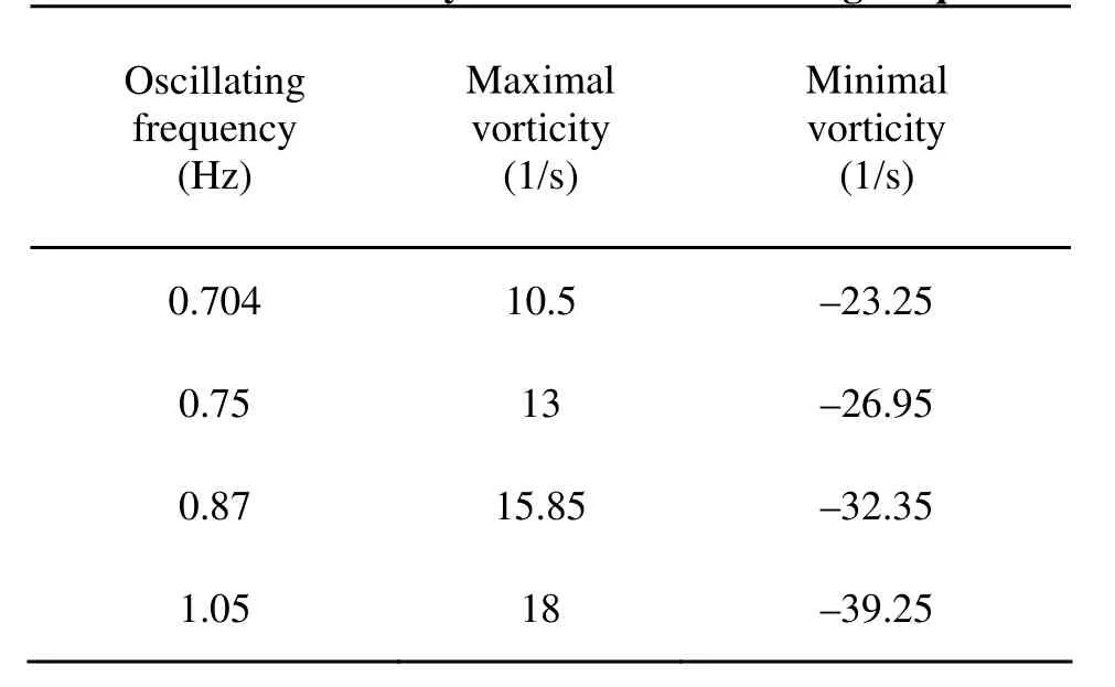
Table 3 Peak of vorticity at different oscillating frequencies
3.3Characteristic of the vorticity field at different Strouhal numbers
The Strouhal number (St=fH/v) is related to flow velocity, oscillating frequency and wake vortex width. In order to discuss the effect of the Strouhal number on the structure of the flow field, the flow field was measured forr the thirty-five cases, in which the oscillating amplitude is 20o, corresponding to the wake vortex width 0.9114 m, the oscillating frequency is respectively taken as 0.75 Hz, 0.835 Hz, 0.91 Hz, 1.05 Hz and 1.17 Hz and the velocity 0.154 m/s, 0.176 m/s, 0.195 m/s, 0.215 m/s, 0.233 m/s, 0.254 m/s and 0.272m/s.Figure 9 presents the vorticity distribution of oscillating caudal fin atSt=0.35, 0.39, 0.43, 0.47, 0.54, 0.6. As is shown in Fig.9, the Strouhal number has a significant influence on the vorticity strength, location and spacing of the wake vortices. Figure 10 presents the curve of the center distance of vortex pair changing withSt. In the graph,Lrepresents thecenter distance of vortex pairs. Figure 11 gives the curve of the angle between connection line of vortex pair and the flow direction. In the graph,βrepresents the angle between connetction line of vortex pair and the flow direction. With the increase ofSt, the center distance of vortex pair is decreased and the formation of vortex pairs speed up. When the Strouhal number is smaller than 0.49, the angle between connection line of vortex pair and the flow direction is greater than 50o. Namely as the angle between jet velocity and flow velocity is smaller, the thrust component is larger.

Fig.9 Vorticity field at different Strouhal numbers

Fig.10 Variation of vortex pair interval
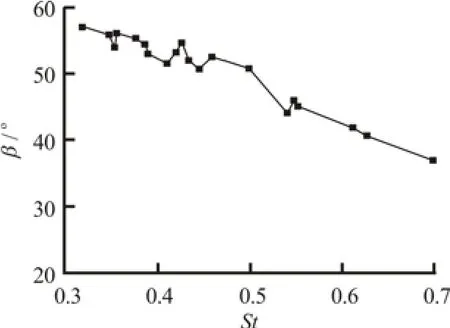
Fig.11 Variation of included angle beween flow direction and line linking vortex pair centers

Fig.12 Vorticity field in 0-0 plane
3.4Model of 3-D vortex ring chain of flexible oscillating caudal fin
3.4.1 Relation between the position of oscillating fin and characteristic of wake vortex
Figure 12 shows the vorticity field in the 0-0 plane at the different positions with the frequency 0.835 Hz, and the direction of vortex pairs in Fig.12(b) is opposite to that of Fig.12(a), in addition, the vorticity in both conditions keeps the same. The negative vortex in Fig.12(a) is the starting vortex which is rolled up on the lee sides of caudal fin oscillating from right side to left side, and the positive vortex in Fig.9 is shed from the cross side of caudal fin oscillating to the middle side.
3.4.2 Velocity circulation and geometrical properties of vortex ring
In order to describe the geometrical properties of 3-D vortex ring of the caudal fin, the shape and the size of vortex must be determined. According to the Stokes theorem, the ring affected by the vortex can be determined by calculating the radial distribution of velocity circulation. When the velocity circulation reaches the maximum, the radius corresponding to the peak value is the vortex radius. The velocity circulation is defined as

The selection of calculation path is shown in Fig.13.
Figures 14 and 15 show the radial distribution of the velocity circulation in the vorticity field in the 0-0 plane with the oscillating frequency 0.835 Hz and at the position of left 13.5o. The peaks of velocity circulation of the red vortex and the blue vortex are 21652 mm²/s and 34653 mm²/s respectively, and their radii are both 30 mm accordingly. So the influence radius in this condition is 30 mm.
According to the analysis in Section 3.1, in the different sections of the caudal fin, the vortex distance is gradually decreasing away from the center plane. In the different sections of fin, the flow field keeps the shape of vortex pair, and the value of velocity circulation is almost identical, while the relative position and distance of vortex pairs vary. The model of 3-D vortex ring is constructed through linking vortices with the radius of 30 mm in different planes along the spanwise direction. As the oscillating frequency is 0.835 Hz, the vortex distance is 158.6 mm and the radius is 30 mm. Hence corresponding to the 3-D vortex ring, its internal and external diameters are 128.6 mm and 188.6 mm respectively. The shape of the vortex ring is assumed as a circle.
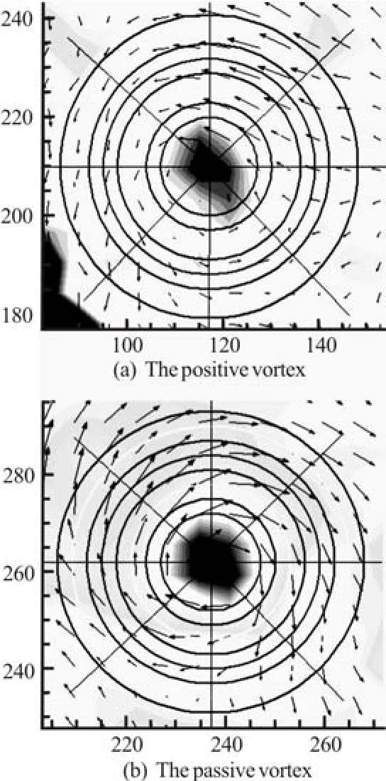
Fig.13 Calculation path of velocity circulation

Fig.14 Velocity circulation of negative vortex
With the evolution of the vortex, vortex rings will continue to move toward the downstream, so vortex ring chain is formed. Figures 16 and 17 present the relationship of the geometry of vortex chain, the vorticity and oscillating position, and the zigzag chain is composed by a series of vortex pairs. Obviously, the central vortex ring creates a jet, and the velocity component of the jet flow along the advancingdirection produces the thrust of the oscillating caudal fin. Because the spanwise length of caudal fin is 175 mm, the diameter of 3-D vortex ring and the span length of the caudal fin almost keep the same, and the shape of the vortex ring is near a circle.

Fig.15 Velocity circulation of positive vortex

Fig.16 Top view of vortex chain
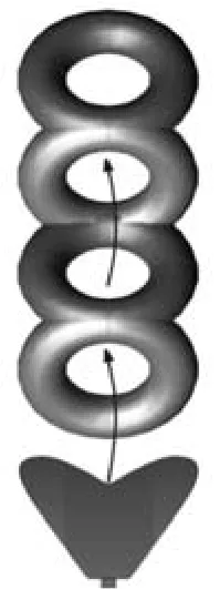
Fig.17 Side view of vortex chain
Especially, the 3-D vortex rings provide not only the horizontal thrust and lateral oscillating force, but also the small vertical components, namely the lift. It indicates that the 3-D vortex ring is not perpendicular to the plane strictly, but must have a little oblique angle. The oblique angle of vortex ring could be determined according to the coordinates of vortex centers. The oblique angle of vortex ring is 9.85oat the oscillating frequency 0.835 Hz, This conclusion is proved by the experimental results of Lau[4].
4.Conclusions
The experiments with the DPIV have been carried out to study the characteristics of the flow field of flexible oscillating caudal fin. The average velocity of flow field from the different film planes is presented for different oscillating positions and frequencies. It is found that the vortex flow fields exhibit significant difference in properties in different sections along the spanwise direction of caudal fin. Through the analysis of the vorticity field of the spanwise in the midpoint plane of the caudal fin with the oscillating positions of 13.5oleft, the effects of oscillating frequency of caudal fin on the vortex distance and vorticity magnitude have been investigated,
In order to describe the geometrical properties of 3-D vortex ring of the caudal fin, the radius affected by the vortex is determined by calculating the radial distribution of the velocity circulation. According to the results of the vortex distance, the geometry size and the vertical oblique angle of 3-D vortex ring are presented, and then the model of 3-D vortex ring chain of flow field of oscillating caudal fin is constructed. The model gives the quantitative relationship of the oscillating parameter and the wake vortex structure of the caudal fin, and it elucidates the wake field properties produced by the oscillating caudal fin of actual fish swimming. Therefore, it provides the research foundation for establishing the analysis model of oscillating parameters, the flow field structure and the thrust of caudal fin.
[1] TONG Bing-gang, LU Xi-yun. A review on biomechanics of animal flight and swimming[J].Advances in Mechanics.2004, 34(1): 1-8(in Chinese).
[2] Daichin, ZHAO Li-li. PIV measurement of wake flow of an airfoil near free surface and the POD analysis[J].ChineseJournal of Hydrodynamics,2008, 23(2): 196-203(in Chinese).
[3] LI Hai-feng, CHEN Hong-xun. Experimental and numerical investigation of free surface vortex[J].Journal of Hydrodynamics,2008, 20(4): 485-491.
[4] LAU T. C. W., KELSO R. M. and HASSAN E. R. Flow visualization of a pitching and heaving hydrofoil[C].The 15th Australasian Fluid Mechanics Conference.Sydney, Australia: The University of Sydney, 2004, 13-17.
[5] HOVER F. S., TRIANTAFYLLOU M. S. Effect of angle of attack profiles in flapping foil propulsion[J].Journal of Fluids and Structures,2004, 19(1): 37-47.
[6] SCHOUVEILER L., HOVER F. S. and TRIANTAFYLLOU M. S. Performance of flapping foil propulsion[J].Journal of Fluids and Structures,2005, 20(7): 949-959.
[7] WANG Zhao, SONG Hong-jun and YIN Xie-zhen. The visualization of vortex field of unsteady motion for2D foil-heaving motion[J].Experiments and Measurements in Fluid Mechanics,2004, 18(2): 71-76(in Chinese).
[8] LIU Zhen, HYUN Beom-soo and KIM Moo-rong et al. Experimental and numerical study for hydrodynamic characteristics of an oscillating hydrofoil[J].Journal of Hydrodynamics,2008,20(3): 280-287.
[9] HEATHCOTE S., MARTIN D. and GURSUL I. Flexible flapping wing propulsion at zero free stream velocity[C].The 33rd AIAA Fluid Dynamics Conference and Exhibit.Orlando, Florida, USA, 2003, 23-26.
[10] NAUEN J. C., LAUDER G. V. Hydrodynamics of caudal fin locomotion by chub mackerel, scomber japonicus (scombridae)[J].The Journal Experimental Biology,2002, 205: 1709-1724.
[11] MULLER U. K., SMIT J. and STAMHUIS E. J. How the body contributes to the wake in undulatory fish swimming: Flow fields of a swimming eel (anguilla )[J].Journal of Experimental Biology.2001, 204: 2751-2762.
[12] YANG Yi-hong, YIN Xie-zhen and LU Xi-yan. Flow visualization over a 2-D traveling wave wall[J].Journal of Experiments in Fluid Mechanic,2005, 19(2): 84-90(in Chinese).
[13] DRUCKER E. G., LAUDER G. V. Locomotor forces on a swimming fish: Three-dimensional vortex wake dynamics quatified using digital particle image velocimetry[J].Journal of Experimental Biology,1999, 202: 2393-2412
[14] JEFFREY A. W. Dynamics of pectoral fin rowing in a fish with an extreme rowing stroke: The threespine stickleback (gasterosteus aculeatus)[J].Journal of Experimental Biology,2004, 207: 1925-1939.
[15] JING Jun, LI Sheng and LU Xi-yan et al. The kinematic analysis of C-start in crucian carp (carassius auratus) [J].Journal of Experimental Mechanics,2004, 19(3): 276-282(in Chinese).
[16] JING Jun, YIN Xie-zhen and LU Xi-yun. Observation and hydrodynamic analysis on fast-start of yellow catfish (pelteobagrus fulvidraco)[J].Progress in Natural Science,2005, 15(1): 34-40.
November 3, 2009, Revised January 22, 2010)
* Project supported by the National Natural Science Foundation of China (Grant No. 50879031), the Key laboratory of Jiangsu Province (Grant No. CT0701).
Biography:WANG Zhi-dong (1967-),Male, Ph. D., Professor
2010,22(3):393-401
10.1016/S1001-6058(09)60070-6
杂志排行

水动力学研究与进展 B辑的其它文章
- BROADBAND ROTOR NOISE PREDICTION BASED ON A NEW FREQUENCY-DOMAIN FOUMULATION*
- THE EFFECT OF RECLAMATION IN AREAS BETWEEN ISLANDS IN A COMPLEX TIDAL ESTUARY ON THE HYDRODYNAMIC SEDIMENT ENVIRONMENT*
- IMPROVED DEM-CFD MODEL AND VALIDATION: A CONICAL-BASE SPOUTED BED SIMULATION STUDY*
- FLOWS THROUGH ENERGY DISSIPATERS WITH SUDDEN REDUCTION AND SUDDEN ENLARGEMENT FORMS*
- NUMERICAL SIMULATIONS OF WAVE-INDUCED SHIP MOTIONS IN TIME DOMAIN BY A RANKINE PANEL METHOD*
- SENSITIVITY STUDY OF THE EFFECTS OF WAVE-INDUCED VERTICAL MIXING ON VERTICAL EXCHANGE PROCESSES*