IMPROVED DEM-CFD MODEL AND VALIDATION: A CONICAL-BASE SPOUTED BED SIMULATION STUDY*
2010-07-02RONGLiangwan
RONG Liang-wan
Department of Applied Mechanics and Engineering, Sun Yat-sen University, Guangzhou 510275, China,
E-mail: rongliangwan@163.com
ZHAN Jie-min
Department of Applied Mechanics and Engineering, Sun Yat-sen University, Guangzhou 510275, China
Guangdong Province Key Laboratory of Coastal Ocean Engineering, Sun Yat-sen University, Guangzhou 510275, China
IMPROVED DEM-CFD MODEL AND VALIDATION: A CONICAL-BASE SPOUTED BED SIMULATION STUDY*
RONG Liang-wan
Department of Applied Mechanics and Engineering, Sun Yat-sen University, Guangzhou 510275, China,
E-mail: rongliangwan@163.com
ZHAN Jie-min
Department of Applied Mechanics and Engineering, Sun Yat-sen University, Guangzhou 510275, China
Guangdong Province Key Laboratory of Coastal Ocean Engineering, Sun Yat-sen University, Guangzhou 510275, China
An improved and efficient DEM-CFD approach is developed for spouted beds. A nonlinear Discrete Element Method (DEM), with a concept of spring, dash-pot and friction slider, is used for tracing the movement of each individual particle. The gas flow is described by a set of reorganized governing equations. Two phases are coupled through contributions due to effects of porosity, viscosity and drag. All equations are solved with the commercial package Fluent with an implementation of User Defined Functions (UDF). To validate the improved model, a two-dimensional conical-base spouted bed is chosen as a case study. An unstructured mesh system is adopted instead of regular grid system. The simulation also takes the Saffman force and Magnus effect into account. The calculation results show good agreement with the experimental observations which are taken from the literature.
Discrete Element Method (DEM), spouted bed, Fluent User Defined Functions (UDF), unstructured mesh
1. Introduction
Spouted beds provide a means of good mixing of particles and gas-particle contacting for relatively large particles. The spouted bed technique has found applications in many industrial processes, such as catalytic cracking, tablets coating, combustion and granulations of fertilizers and other materials. The successful design and control of a spouted bed requires a better knowledge of the dynamics of the systems and the behaviors of each phase. An advanced experimental technique, such as the Particle Image Velocimetry (PIV), is an expensive approach to makea measurement of these properties. Theoretical studies of gas and solids motion in spouted bed have been conducted by many researchers. A characteristic common to most of these theoretical models is that all interaction forces between phases are lumped into one term through a special approach. The viscous stress terms for both phases are often neglected[1].
The approach based on a computer simulation has been widely used for studying dense particle systems, with an advantage of easily describing detailed and wide range flow properties[2-5]. In recent years, two most commonly used methods in the simulation of multiphase flows are the Two-Fluid Model (TFM) and the discrete element/particle method (DEM/DPM). The TFM approach treats the different phases as interpenetrating continua and a set of equations that have similar structure apply to eachphase. For the DEM/DPM method, the gas phase is described by a locally averaged Navier-Stokes equation, while the motion of each individual particle is traced by a soft-sphere or a hard-sphere model, and two phases are coupled through a term due to inter-phase momentum transfer. Both approaches have been adopted in the simulations of spout beds. The hydrodynamic behavior in spouted bed was presented by many researchers[6-9]with a two-fluid gas-solids flow model. Huilin[10]and Wan[11]gintegrated a kinetic-frictional constitutive model for dense assemblies of solids in the simulation of spouted beds. The model treated the kinetic and frictional stresses of particles additively. Using the TFM method embedded in the commercial CFD simulation package Fluent, Du[12,13]described the influences of the drag coefficient correlations, frictional stress, maximum packing limit and coefficient of restitution of particles on the CFD simulation of spouted beds.
The TFM approach is more feasible for practical application to complex multiphase flows, however, it does not recognize the discrete character of the solid phase, and there has not yet been a quantitative analysis to assess multi-particle microstructures. The DEM/DPM approach offers a more natural way to simulate the systems of spouted bed with complex behavior. Several attempts have been made to model spouted beds using this approach[14-18]. One of the challenges confronting the solution of spouted bed is how to handle the convergence problem induced by the porosity variation. Additionally, one should also pay attention to the boundary condition at the conical surface for the V-shape spouted beds. Several researchers have developed the DEM simulations of a conical-base spouted bed under a regular grid system[19-22]. The accuracy of the simulations will not be guaranteed because additional closure equations are required for their boundary conditions.
In this article, an efficient DEM-CFD model is developed for the spouted beds. The model is incorporated into the commercial Fluent console with a method described by Wu[23,24]. The objective of the present work is to extend the previous simulation techniques under regular grid system to an unstructured mesh system. An advantage of our approach is that it can minimize codes modifications to adapt to spouted beds of arbitrary shape.
2. Governing equations
2.1Particle motion
The motion of each individual particle in the system can be described by Newtonian second law of motion. Thus, at instantt, the translational and rotational motions of particleiwith massmiand volumeViare governed by

wherefciis the particle-particle contact force,βthe inter-phase momentum transfer coefficient,Tithe summation of torque caused by the tangential components of the contact force, andIi, andupiandωpiare the moment of inertia, linear velocity and angular velocity, respectively, of the particle. The forces on the right side of Eq.(1) are respectively due to the pressure gradient, drag, inter-particle contact forces and gravity.
2.2Fluid motion
The continuity and momentum equations for the fluid motion are based on local mean variables, given as

whereuf,fρandεare the fluid velocity, density and the void fraction, respectively,τfis the viscous stress tensor which is assumed to obey the general law for a Newtonian fluid:

where the bulk viscosityfλcan be set to zero for gases.
The interaction between the gas phase and the particles is achieved via the coupling termSp, which is computed from

where ΔVrepresents volume of the mesh where the particles are located. The distribution functionδlocally distributes the reaction force acting on the gas-phase to the Eulerian grid. When the volume of the smallest computational cell for the fluid is much larger than the volume of a particle, the mapping of properties from the Lagrangian particle position to the Eulerian computational grid and vice versa can be done in a straightforward manner through using the volume-weighing techniques[25].
2.3Momentum exchange coefficient
A proper drag model for the description of the momentum exchange coefficientβis vital for an adequate description of fluidized beds. Several drag models have been reported in literature. The drag model that is used most frequently in discrete particle models is a combination of the Ergun equation, originally developed for packed beds, at low porosities (ε<0.8):

and the Wen-Yu relation at high porosities (ε>0.8):

whereCdis the drag coefficient for an isolated spherical particle given by Schiller and Naumann:

2.4Inter-particle collisions
Various types of contact relations are available to describe the interaction between particles. The simplest contact model is the linear contact law in which the spring stiffness is a constant. The nonlinear contact model, an improvement over the linear law, can be made by considering the Hertz theory to obtain the force-deformation relation and is used in this study.
The total contact force and torque acting on particleiin Eqs.(1) and (2) are the summation of forces due to individual neighborjand can be decomposed into their normal (fcn,ij) and tangential (fct,ij) components:

whereRiis the radius of the particle,nijis the unit normal vector between particleiandj.
The equations for forces calculation of the nonlinear contact model are given as follows
Normal force:

In whichδnis the overlap of two particles andδtis the displacement in the tangential direction. The spring coefficientsknandktare calculated from the following equations based on the Hertz and MD contact theory:

whereEsandsσare Young’s modulus and Poisson’s ratio for the solid, respectively.Gsis the shear modulus related to Young’s modulus by

The damping coefficientsnηandtηare determined from the method of Tanaka, given as

whereαis a coefficient related to the restitution coefficient.
3. Numerical strategy
The commercial CFD package Fluent, a powerful tool to solve physical flows with complex domains, is chosen as our simulation platform. It offers a robust Algebraic Multi-Grid (AMG) solver, optional pressure-velocity coupling algorithms and discretization schemes. The UDFs provided by Fluent allows one to add customized features into the console. A limitation of a normal UDF development of the DPM was showed by Wu[23]and a re-arrangement of the flow governing equations was issued to overcome this limitation. Here we use the similar equations re-arrangement with UDF implementation in our DEM-CFD simulation showed below.
If the gas density is assumed as a constant or suffered a subtle change, the continuity equation Eq.(3) can be re-organized as

The term on the right hand side of Eq.(18) represents a mass source due to the porosity variation in time and space caused by the solid phase.
The momentum Eq.(4) is handled with a distinct similarity showed as follows:

We can see that source term Eq.(21) of the re-arranged momentum equation include contributions from the variation of porosity, effects of additional viscous force due to non-uniform distribution of porosity, and contribution from the drag between two phases. The effect of viscous force is small compared with the other two parts and thus can be ignored.
It can be seen that the governing equations of two-phase flow may be reduced to those of single-phase with adding both mass and momentum source terms related to the porosity distribution and variation. Therefore a straightforward UDF could be incorporated into the Fluent console.
One may note that the source term Eq.(21) of the momentum equations should be decomposed into a linearized form to enhance the stability of solution and help to raise convergence rates as follows:


The computational strategy used for our DEM-CFD model is displayed in Fig.1. This figure shows a flow chart of the different modules that constitute the model. The porosity, gradient of porosity, and drag coefficient should be prepared before the solution of the governing equations of the gas phase starts. With the computed gas flow field, a DEM module is performed to update the properties of each individual particle.

Fig.1 Flow chart of improved DEM-CFD model computation
4. Validation
In order to show the applicability of our improved DEM-CFD model to the spouted beds with irregular boundaries, a common type of V-shape is considered here. We perform a two-dimensional simulation of the experiment conducted by Zhao[18]. The computed region is filled with a number of 894 unstructured elements. The gas velocity is significant between the central spout region and the annular dense region in a spouted bed. The Saffman lift force due to large gas velocity gradient should not be neglected and is calculated by the Mei empirical fit

The Magnus lift force due to the velocity difference between the different sides of the particle may be also taken into account and is calculated as follows[26]:


Table 1 Parameters used for the present simulation
Initially, all particles with an equal diameter are randomly positioned in the domain and allowed to fall down only under gravity. A stable packing with a static height of 100 mm can be attained after sufficiently long time. The packing configuration is finally used as the initial input data for our simulation. The parameters chosen for the present simulation are provided in Table 1.

Fig. 2 Time series of bed pressure drop
The residual of the computation will decrease to an order of 10-4after 30 iterations in each flow time step. The convergence history demonstrates a good stability. Figure 2 shows the result of the bed pressure drop varying with time. Two distinct regions can be identified: the start-up (t<0.7s) and stable fluidization stages. Compared with the bed pressure drop at the stable stage, a much higher value is detected at the start-up region because the need to overcome the inter-particle locking and friction. Figure 3 is a plot of the particles distribution at the start-up stage. The particles are pushed to both laterals and a bubble forms at the center having a shape of the domain. When the lateral particles slide along the V-shape wall and back to the bottom of the bed, the stable fluidization stage follows. An oscillation cycle period of 130 ms-150 ms can be identified from the second stage in Fig.2, a little shorter than that of 150 ms-160 ms observed in the experiment[18].

Fig. 3 Particles distribution at the start-up stage
Typical flow pattern of particles at different time in the conical-base spouted bed are showed in Fig.4. Three distinct characterized regions, i.e., the spout, annulus and fountain flow regions, can be clearly identified. In a stable flow stage, a “neck” marked with dense particles can be found in the central spout area. The neck starts at the zone near the inlet, moves upwards with the incoming gas and finally disappears at the end of the spout. The particles in the neck region move with a highest speed compared to those in other regions. They appear as a group instead of individual particles. As the neck moves upwardg, additional particles from the annulus can be entrained and make the neck grow progressively denser. The spout becomes almost “choked” when they approach the end of the spout. Finally the choked particles will scatter in an axial direction like an explosion. The patterns of particles flow described above agree well with the experimental observations by Zhao[18].
Figure 5(a) indicates a comparison of longitudinal distribution of particle vertical velocity on the spout midline to the experiment and the simulation by Zhao[18]. It can be seen that the particles entrained from the annulus near the inlet accelerate in a short time. The maximum particle vertical velocity evaluated in this study is 1.1 m/s, a bit higher than that in the experiment. Then particles decelerate gradually in the fountain zone. Our simulation evaluates a much higher particle vertical velocity in the fountain region and particles thus reach a larger maximum altitude of 180 mm, compared to 155 mm of the experimental observation. This may be due to the coarse evaluation of the real porosity with the 2-D to 3-D transformed correlation showed below

Hence underestimation of the porosity will cause the drag over-predicted with the Gidspow empirical correlation. Furthermore, the trend of the particle vertical velocity curve of our simulation is quite similar to that of the simulation performed with a three-dimensional DPM method by Wu[23].
A comparison of the lateral profile of particle vertical velocity in the spout region between the simulations and experiments at various bed levels is showed in Fig.5(b). The simulations agree well with the experiments at all bed heights.

Fig. 4 Flow patterns of particles in conical-base spouted bed
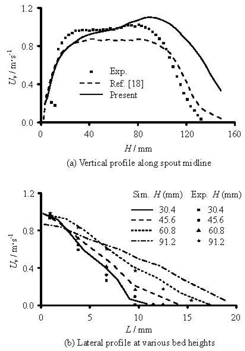
Fig.5 Distribution of particle vertical velocities in the spout
Figure 6(b) outlines the experimental spout borders where vertical particle velocity is zero. The spout width of this simulation yielded from both the borders is larger than that of the experiments, as showed in Fig.6(a). The largest difference, located at the upper end of the spout, is approximately 15 mm. Figure 6(a) also shows the time-average particle velocity vectors. It can be seen that the particle velocity magnitude in the spout is quite large, about 9 times of that in the annulus, which also well agreeswith the experimental observation.

Fig.6 Spout contour and time-averaged flow fields of particles in conical-base spouted bed
5. Conclusion
An efficient DEM-CFD model for spouted beds has been developed by a combination of the discrete element method and a set of re-organized governing equations for the gas phase. The flows of two phases are solved by the Fluent package with a UDF implementation under an unstructured mesh system. The effectiveness of the present model is demonstrated through a simulation of particle motion and gas flow pattern in a two-dimensional conical-based spouted bed. The numerical simulation shows that the computational procedure is of good stability and convergence. The results are compared with measurements reported in literature and also with other researchers’ simulation results. The characteristic particle flow patterns and spouted-bed behaviors, such as annulus, spout and fountain, are reproduced in our simulation. The present investigation predicts a similar oscillation cycle period to the measurement. Particle velocity profiles in the spout and annulus are found to agree with the experimental observations, but a larger value for those in the fountain region. The spout width identified by our simulation is a bit larger than that in the experiment.
Acknowledgement
The authors wish to thank Dr. Wu Chun-liang of Guangdong Ocean University for useful discussions.
[1] HUILIN L., YONGLI S. and YANG L. et al. Numerical simulations of hydrodynamic behaviour in spouted beds[J].Chemical Engineering Research and Design,2001, 79(5): 593-599.
[2] WANG Li-yang, ZHENG Zhi-chu and WU Ying-xiang et al. Numerical and experimental study on liquid-solid flow in a hydrocyclone[J].Journal of Hydrodynamics,2009, 21(3): 408-414.
[3] WU Chun-liang, ZHAN Jie-min. Numerical prediction of particle mixing behavior in a bubbling fluidized bed[J].Journal of Hydrodynamics, Ser. B,2007, 19(3): 335-341.
[4] XIE Ming-liang, ZHOU Huai-chun and ZHANG Yindi. Hydrodynamics stability of bickley jet with particle laden flow[J].Journal of Hydrodynamics,2009, 21(5): 608-613.
[5] ZHANG Jin-feng, ZHANG Qing-he. Hydrodynamics of fractal flocs during settling[J].Journal of Hydrodynamics,2009, 21(3): 347-351.
[6] DUARTE C. R., MURATA V. V. and BARROZO M. A. S. A study of the fluid dynamics of the spouted bed using CFD[J].Brazilian Journal of Chemical Engineering,2005, 22(2): 263-270.
[7] GRYCZKA O., HEINRICH S. and DEEN N. G. et al. Characterization and CFD-modeling of the hydrodynamics of a prismatic spouted bed apparatus[J].Chemical Engineering Science,2009, 64(14): 3352-3375.
[8] WANG Z. G., BI H. T. and LIM C. J. Numerical simulations of hydrodynamic behaviors in conical spouted beds[J].China Particuology,2006, 4(3-4): 194-203.
[9] WU Z. H., MUJUMDAR A. S. CFD modeling of the gas–particle flow behavior in spouted beds[J].Powder Technology,2008, 183(2): 260-272.
[10] HUILIN L., YURONG H. and WENTIE L. et al. Computer simulations of gas–solid flow in spouted beds using kinetic–frictional stress model of granular flow[J].Chemical Engineering Science,2004, 59(4): 865-878.
[11] SHUYAN W., XIANG L. and HUILIN L. et al. Numerical simulations of flow behavior of gas and particles in spouted beds using frictional-kinetic stresses model[J].Powder Technology,2009, 196(2): 184-193.
[12] DU W., BAO X. and XU J. et al. Computational fluid dynamics (CFD) modeling of spouted bed: Assessment of drag coefficient correlations[J].Chemical Engineering Science,2006, 61(5): 1401-1420.
[13] DU W., BAO X. and XU J. et al. Computational fluid dynamics (CFD) modeling of spouted bed: Influence of frictional stress, maximum packing limit and coefficient of restitution of particles[J].Chemical Engineering Science,2006, 61(14): 4558-4570.
[14] LINK J. M., CUYPERS L. A. and DEEN N. G. et al. Flow regimes in a spout–fluid bed: A combined experimental and simulation study[J].Chemical Engineering Science,2005, 60(13): 3425-3442.
[15] TAKEUCHI S., WANG S. and RHODES M. J. Discrete element study of particle circulation in a 3-D spouted bed[J].Chemical Engineering Science,2005, 60(5): 1267-1276.
[16] TAKEUCHI S., WANG S. and RHODES M. Discrete element simulation of a flat-bottomed spouted bed in the 3-D cylindrical coordinate system[J].Chemical Engineering Science,2004, 59(17): 3495-3504.
[17] ZHAO X. L., LI S. Q. and LIU G. Q. et al. Flow patterns of solids in a two-dimensional spouted bed with draft plates: PIV measurement and DEM simulations[J].Powder Technology,2007, 183(1): 79-87.
[18] ZHAO X. L., LI S. Q. and LIU G. Q. et al. DEM simulation of the particle dynamics in two-dimensional spouted beds[J].Powder Technology,2008, 184(2): 205-213.
[19] KAWAGUCHI T., SAKAMOTO M. and TANAKA T. et al. Quasi-three-dimensional numerical simulation of spouted beds in cylinder[J].Powder Technology,2000, 109(1-3): 3-12.
[20] LIMTRAKUL S., BOONSRIRAT A. and VATANATHAM T. DEM modeling and simulation of a catalytic gas–solid fluidized bed reactor: A spouted bed as a case study[J].Chemical Engineering Science,2004, 59(22-23): 5225-5231.
[21] SWASDISEVI T., TANTHAPANICHAKOON W. and CHARINPANITKUL T. et al. Prediction of gas-particle dynamics and heat transfer in a two-dimensional spouted bed[J].Advanced Powder Technology,2005, 16(3): 275-293.
[22] ZHONG W., XIONG Y. and YUAN Z. et al. DEM simulation of gas–solid flow behaviors in spout-fluid bed[J].Chemical Engineering Science,2006, 61(5): 1571-1584.
[23] WU C. L., BERROUK A. S. and NANDAKUMAR K. Three-dimensional discrete particle model for gas-solid fluidized beds on unstructured mesh[J].Chemical Engineering Journal,2009, 152(2-3): 514-529
[24] WU C. L., ZHAN J. M. and LI Y. S. et al. Dense particulate flow model on unstructured mesh[J].Chemical Engineering Science,2006, 61(17): 5726-5741.
[25] DEEN N. G., Van SINT ANNALAND M. and Van Der HOEF M. A. et al. Review of discrete particle modeling of fluidized beds[J].Chemical Engineering Science,2007, 62(1-2): 28-44.
[26] MICHAELIDES E.Particles, bubbles and drops: Their motion, heat and mass transfer[M]. Singapore: World Scientific Publish Co. Inc., 2006.
September 23, 2009, Revised March 30, 2010)
* Biography: RONG Liang-wan (1980-), Male, Ph. D.
ZHAN Jie-min,
E-mail: stszjm@mail.sysu.edu.cn
2010,22(3):351-359
10.1016/S1001-6058(09)60064-0
杂志排行

水动力学研究与进展 B辑的其它文章
- A MULTI-SCALE APPROACH FOR THE ANALYSIS OF PROPER SAMPLED DATA SCALE IN HOT-WIRE EXPERIMENT OF SQUARE DUCT FLOW*
- SENSITIVITY STUDY OF THE EFFECTS OF WAVE-INDUCED VERTICAL MIXING ON VERTICAL EXCHANGE PROCESSES*
- ANALYTICAL STUDY OF WAVE MAKING IN A FLUME WITH A PARTIALLY REFLECTING END-WALL*
- BROADBAND ROTOR NOISE PREDICTION BASED ON A NEW FREQUENCY-DOMAIN FOUMULATION*
- NUMERICAL SIMULATIONS OF WAVE-INDUCED SHIP MOTIONS IN TIME DOMAIN BY A RANKINE PANEL METHOD*
- FLOWS THROUGH ENERGY DISSIPATERS WITH SUDDEN REDUCTION AND SUDDEN ENLARGEMENT FORMS*