Features of PBB-TEArchitecture and GMPLSControl Technology
2010-06-05WeiJianwenXieRuiJinYaohui
WeiJianwen,Xie Rui ,Jin Yaohui ,
(1.The state key lab of advanced optical communication systems&networks,Shanghai Jiao Tong University,Shanghai200030,P.R.China;
2.Network&Information Center of Shanghai Jiao Tong University,Shanghai200240,P.R.China)
Abstract:Time Division Multiplexing(TDM)transport networks are evolving to packet-oriented,and a variety of carrier-class packet transport technologies have emerged.Provider Backbone Bridge with Traffic Engineering(PBB-TE)is a connection-oriented packet transport technology that provides good scalability and manageability,and guarantees Quality of Service(QoS).Generalized Multi-Protocol Label Switching(GMPLS)is a mature transport network control plane technology that supports multiple data planes with different switching granularity.GMPLS-controlled PBB-TEis a promising solution for Packet Transport Networks(PTN).
This work was funded by the National Basic Research Program of China(“973”Program)under Grant No.2010CB328205,the National Natural Science Foundation of China under Grant No.60825103,and the National Key
Technology R&D Program under Grant No.2008BAH37B03.
B ackbone Bridge Traffic Engineering(PBB-TE)is a connection-oriented packet transport technology with good scalability and end-to-end QoS support.It contains an Operation,Administration and Maintenance(OAM)mechanism on the data plane.This enhances the reliability and manageability of telecom networks.PBB-TEis expected to be the preferred solution to metro Packet Transport Networks(PTNs).
1 Features of PBB-TE Architecture
1.1 Evolution of IEEE Ethernet
1.1.1 802.1Q Virtual Local Area
Network(VLAN)In IEEE 802.1Q[1],a Customer Virtual LAN Tag(C-Tag)domain based on the frame structure of 802.1 Ethernet is introduced.C-Tag contains a 12-bit Customer Virtual LAN ID(C-VID)and a 3-bit Customer Product ID(C-PID).The C-VID indicates which VLAN the source host belongs to,and C-PID shows the service type of a frame.In a 802.1Q system,physical networks can support up to 4,096 VLANs,and traffic in different VLANs is separated.Depending on the service type indicated by C-PID,the 802.1Q network bridge can offer differentiated services.
1.1.2802.1adProviderBridge(PB)IEEE 802.1ad PB[2]is th e f i rst provider-oriented Ethernet bridge technology.In PB,a Service VLAN Tag(S-Tag)domain is added to the 802.1Q frame structure for service providers.This domain contains 12-bit provider VLAN identifiers(S-VID)and a 3-bit C-PID.An IEEE 802.1ad bridge network is called Provider Bridge Network(PBN).As shown in Figure 1,an S-Tag is either assigned or removed at the entry node of a PBN.The S-Tag separates provider VLAN from customer VLAN,and allows multiple customer VLAN services to be transported through the same provider VLAN.
Limited by the length of the S-VID,PBN supports up to 4,096 services.It forwards frames in the format
1.1.3 802.1ah Provider Backbone Bridge(PBB)
In IEEE 802.1ah PBB[3],a Provider Backbone Bridge Network(PBBN)based on PBN is established to improve PB scalability.A PBB frame has a provider frame header
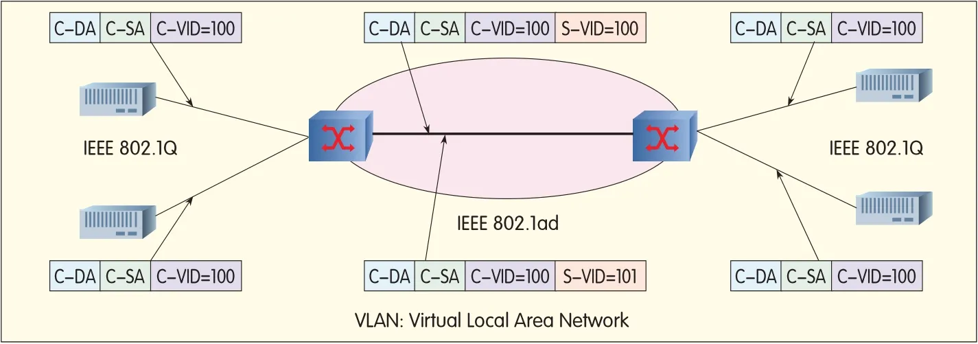
▲Figure 1.Provider VLANis separated from customer VLANin 802.1ad.
1.2 Features of 802.1Qay PBB-TE
Aproduct of PBB and telecom network features,IEEE 802.1Qay PBB-TE[4]is a type of connection-oriented packet transport technology.PBB-TEnetwork architecture,as shown in Figure 2,has the following features:
(1)Scalability
On the data plane,PBB-TEhas the same MAC-in-MAC frame structure as PBB.The core node of a PBB-TE network forwards frames in the format
(2)Connection-Orientation and QoS Guarantee
PBB-TEdiscards the spanning tree protocoland source address learning mechanism,as well as the frames of unknown addresses.Ethernet Switched Path(ESP)is used for transport services and should be established by the control plane or management system.PBB-TEis therefore connection-oriented with each ESP having definite TEattributes and QoS guarantee.
(3)OAM
Using a Connectivity Fault Management(CFM)[5]OAM mechanism,PBB-TEcan provide carrier-class OAM without assistance from other layers.
(4)End-to-End Path Protection
PBB-TEprovides point-to-point and point-to-multipoint ESPwith 1:1 path protection.A protection path can be built while simultaneously building a working path,and by pre-configuring the protection path,QoSidentical to the working path can be achieved.PBB-TE path fault diagnosis and protection triggering are all completed on the data plane,and protection switching time can reach 50 ms.
(5)Multi-Service Bearing
PBB-TEcan bear L2 and L3 services,and also supports TDM services.However,compared to Transport Multiprotocol Label Switching(T-MPLS),PBB-TEhas weaker Multipoint-to-Multipoint(MP2MP)service support,and its QoS classification and controlplane technology are not developed enough.
These weaknesses are expected to be solved during the PBB-TE standardization process.PBB-TE reduces MAN maintenance costs in the long run,and some operators have already tried deploying PBB-TE systems[6].
1.3 PBB-TEEquipment Interconnection Test in Shanghai Jiao Tong University Backbone Network
A cost-effective carrier-class packet transport technology,PBB-TEcan be applied not only in simple MANs,but also in complex scenarios(such as data centers or R&D backbone networks with intensive services and a large number of nodes).The Network Center of Shanghai Jiao Tong University has attempted to apply PBB-TEinto the campus backbone network,and the success of this test will verify the interoperability of PBB-TE and MPLSequipment.In the campus backbone network shown in Figure 3,the core network consists of a series of IP/MPLSrouters interconnected by 10GEor GErouters.The convergence network consists of IP routers.The campus network offers services such as on-demand and multicast intra-campus video,email,File Transfer Protocol(FTP),and P2P file sharing.To provide better service,the network uses MPLS-TEtechnology in a number of areas.Aspecific service-oriented MPLSVirtual Private Network(VPN)has also been created to provide university administration with a reliable and confidentialnetwork platform.
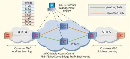
▲Figure 2.PBB-TEarchitecture.
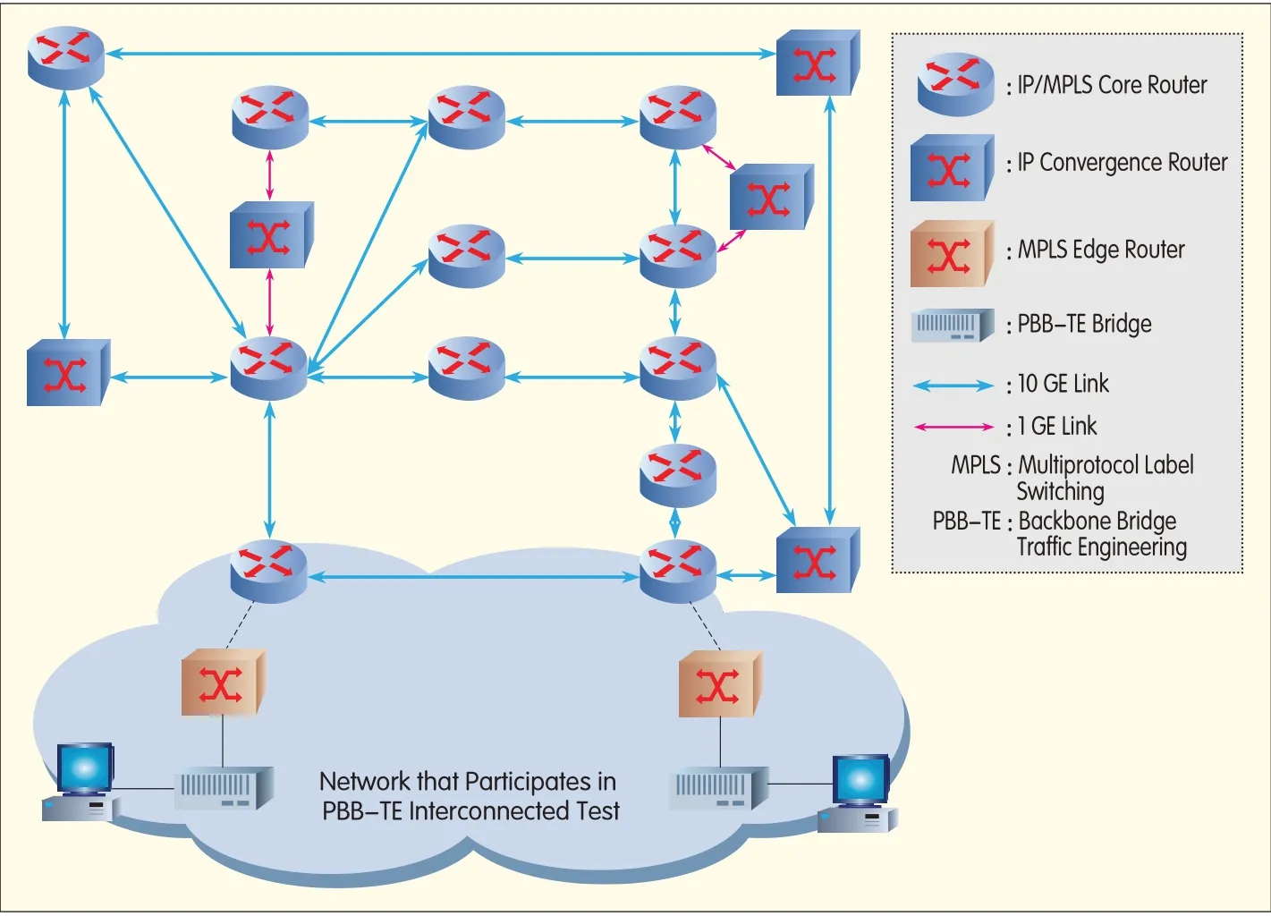
▲Figure 3.PBB-TEInterconnected Testing System in the Backbone Network of Shanghai Jiao Tong University.
In the test,the customer MAC frame was encapsulated as the MAC-in-MACframe after the bridge convergence of PBB-TE.The frame was then encapsulated as an MPLS packet at the MPLSedge node,and transported by the MPLScore network.The frame arrives at the host through the MPLSedge router and PBB-TE bridge at the entry of the MPLScore network.The PBB-TEbridge is a PBB-TEedge bridge with convergence capability.
The test willbe deemed successful when a PBB-TEconvergence network has been established.The network center intends to evaluate the feasibility of PBB-TEin the campus network by comparing the PBB-TEconvergence network with the existing IP convergence network.Astudy of the PBB-TEcontrol plane will also be conducted on equipment connected to MPLSswitches.
2 GMPLS Controlled PBB-TE
Although PBB-TEcontrol plane standards are still being studied,industry has generally agreed to use GMPLSas the PBB-TEcontrolplane technology.GMPLSextends the meaning of label and label exchange in MPLS,and reuses part of the MPLS protocol.GMPLSfunctions include signaling,routing,path selection,and link management.With extensions,GMPLSmay support data planes such as SONET/SDH,Optical Transport Network(OTN),and Wavelength Division Multiplexing(WDM).
2.1 GMPLSControlled of Ethernet Label Switching(GELS)
IETFis a leading promoter of standardization of GMPLS-controlled PBB-TE.While standardization is far from complete,two GELSdrafts have been released[7].These drafts involve GELSarchitecture and technical specifications.GELSuses as many of the original GMPLcomponents as possible,and makes necessary extensions.
(1)Addressing Mode
The node on the GELScontrol plane stilluses the IPaddress ID,and control plane messages are exchanged on the IPlayer.GELSsupports both labeled and unlabeled ports.
(2)Signaling Protocol
A new labelformat
(3)Traffic Parameters
GELSuses four bandwidth parameters[8]:Committed Information Rate(CIR),Committed Burst Size(CBS),Excess Information Rate(EIR),and Excess Burst Size(EBS).
(4)Route and Path Computation
GMPLSdoes not limit path selection methods.Therefore,it allows computation and selection of any path.Open Shortest Path First with Traffic Engineering Extensions(OSPF-TE)and Intermediate System to Intermediate System Extensions for Traffic Engineering(IS-IS-TE)can still be used to release routing messages of the PBB-TEdata plane.Because of labeled or unlabeled data plane ports,routing messages need not carry MAC addresses of ports.
(5)Link Management
GMPLSLink Management Protocol(LMP)and PBB-TECFM have some overlapping functions.For example,both can implement neighbor discovery,fault diagnosis,fault confirmation,and fault positioning.CFM can work independently without support from other layers,while LMP can allocate numbered/unnumbered interface IDs automatically.CFM and LMPcan therefore run together.The two IETFdrafts only specify how GMPLSis used to build point-to-point PBB-TEpaths.Improvements are required in the specifications of point-to-multipoint path establishment and control-plane-based protection recovery.802.1aq Provider Link State Bridging(PLSB)is also a solution for PBB-TEcontrol[9].
2.2 Simulation Platform of GMPLS Controlled PBB-TE
Researchers are likely to use a virtual PBB-TEtesting platform rather than a platform built with real PBB-TE equipment because a virtualplatform is more flexible and supports more nodes.Such virtual platforms are of two types:
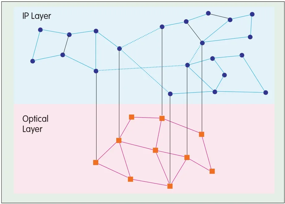
◀Figure 4.Screenshots of the Platform for Large-Scale Optical Network Validation.
(1)Emulation
An emulation platform is represented by Finite State Machine(FSM)emulation software such as Network Simulator 2(NS2).It supports a large number of nodes and has good scalability;however,it lacks details of signaling interaction,and fidelity of the control and data planes is not good enough.
(2)Simulation
The simulation platform is represented by the DRAGON program[10],and uses computers to replace PBB-TEbridges.The complete GMPLSprotocolstack is run in the computers,and data frames are sent through the network cards.Therefore,the PBB-TEcontroland data planes can be realistically simulated.Scalability is limited because one PBB-TEbridge requires one computer for simulation.
This paper focuses on signaling interworking and cross-layer optimization of GMPLS,and so a compromise is made between emulation and simulation.As shown in Figure 4,the large-scale optical network validation platform simulates a 2-layer network,with PBB-TEon the upper layer and SONET/SDH on the bottom layer.Resource Reservation Protocol-Traffic Engineering(RSVP-TE)and OSPF-TEare implemented completely on the platform,as are the GMPLSextensions to PBB-TEand SONET.The platform does not implement the forwarding function on the data plane.Anode on the platform is only an object in the computer’s memory;signaling interaction between nodes as wellas routing message updates are implemented by communications between objects,without the need for actual network cards.Both the signaling and routing messages are recorded in logs for offline reading.The platform is intended to successfully demonstrate cross-layer path establishment where tens of nodes are involved.GMPLSextensions are to be implemented on the platform for support of PBB-TEprotection switching.
3 Conclusion
PBB-TEis a PTN technology with layered architecture,improved OAM,and QoSguarantee.As a convergence-layer solution,PBB-TEis more cost effective than MPLS.PBB-TEand GMPLSstandards are still in progress,and more telecom network characteristics will be introduced into the PBB-TEsystem.With improved standards,PBB-TEis expected to become an optimal solution for next-generation metro PTNs.
杂志排行

ZTE Communications的其它文章
- Standardization Progress of Packet Transport Networks
- Several Issues in the Development of Packet Transport Networks
- Ring Protection and Survivability Mechanisms for Packet Transport Networks
- Service Adaptation and Label Forwarding Mechanism for MPLS-TP
- PTN Clock Synchronization Technology and Its Applications
- PTN and IP-Based Mobile Backhaul