Numerical Simulation of Flameless Premixed Combustion with an Annular Nozzle in a Recuperative Furnace*
2010-03-22MIJianchun米建春LIPengfei李鹏飞andZHENGChuguang郑楚光StateKeyLaboratoryofTurbulenceandComplexSystemsDepartmentofEnergyResourcesEngineeringCollegeofEngineeringPekingUniversityBeijing0087China
MI Jianchun (米建春)**, LI Pengfei (李鹏飞) and ZHENG Chuguang (郑楚光)2 State Key Laboratory of Turbulence and Complex Systems, Department of Energy & Resources Engineering,College of Engineering, Peking University, Beijing 0087, China
2 State Key Laboratory of Coal Combustion, Huazhong University of Science and Technology, Wuhan 430074, China
1 INTRODUCTION
Increasing energy efficiency has been acknowledged to be an important issue related to reduction of emissions of greenhouse gases (e.g. CO2) and pollutions (e.g., NOxand SOx) from industry combustion [1, 2].Moderate or Intense Low-oxygen Dilution (MILD)combustion is thus one of the most important achievements in combustion technology recent years.This technology, developed from laboratory tests to industrial applications, can play a significant role in the mitigation of combustion-generated pollutants(NOx, in particular) and greenhouse gases, whilst satisfying thermal efficiency needs. The essence of the technology is that fuel is oxidized in an environment where the oxygen is highly diluted by a substantial amount of inert flue gases and temperature is above that of auto-ignition. Under these conditions traditional flames cannot be sustained and blow-off occurs due to very strong shear motion caused by high jet momentum and strong internal gas recirculation.Chemical reactions occur in a distributed zone with a reduced peak temperature [3, 4]. As a consequence, the temperature distribution is nearly uniform, the net radiation flux can increase by as much as 30% [5],and pollutant emissions, NOxin particular, are much lower than that from conventional flames. Hence uniformity of both the temperature and the chemical species fields are distinct characteristics of the MILD technology.
In the literature this combustion is also given different names. Some relied on a descriptive form of the resulting combustion process, i.e. ‘Flameless Oxidation’ (FLOX) or ‘Colourless Distributed Combustion’ (CDC) since no visible flame front develops [3].If high air preheating is used, the combustion is named ‘High Temperature Air Combustion’ (HiTAC or HTAC) [5]. We use the term ‘MILD combustion’throughout this paper.
A good volume of work has been published on MILD combustion and reviewed by Cavaliere and de Joannon [4] and Tsuji et al [5]. Gaseous, liquid and solid fuels were investigated and some commercial products have been available for more than one decade [6, 7]. Further application of this combustion to waste-to-energy technologies is also underway [8].Cavaliere and de Joannon [4] highlighted the current knowledge in the field and emphasised on two main points: (1) the MILD combustion regime is different from those of other combustions and (2) this combustion applies for a narrow range of temperature that allows design, optimization and adjustment in the process by fine tuning external parameters.
Although numerous fundamental and practical studies have been performed, fuel-air premixing as a way to achieve MILD combustion has received little attention.Wünning & Wünning [3] noted that use of premixed air-fuel reactants under some particular conditions can achieve this combustion. If the mixture can be far off stochiometry, there will be the opportunity to control the temperature in a combustion chamber by the stoichiometric conditions rather than withdrawing energy [3].
On the CFD modelling side, Wünning &Wünning [3] validated that MILD combustion can be calculated with existing CFD simulation codes. Christo and Dally [9] carried out a detailed CFD study of jet in hot co-flow (JHC) burner which was designed to emulate MILD combustion regime. They concluded that the eddy dissipation concept (EDC) model with a detailed kinetic scheme offers best results. More recently, numerical modeling of MILD combustion for LPG and pulverized coal have also performed [10-12]. The flow fields as well as the temperature and oxygen fields were well predicted. Until now, MILD combustion has been widely investigated by CFD and some of numerical modelling results have been verified by experiments.
Our previous CFD work [13] has revealed that,for non-premixed fuel and air jets, there is a critical rate of the initial total reactant momentums below which the MILD combustion does not occur. This was confirmed by experiments in the same study [13].
The present study is aimed at investigating the effect of the momentum rate of inlet premixed air and fuel (natural gas) on MILD combustion. The main objective is twofold: (1) to identify the relationship of flue-gas recirculation with the momentum rate and (2)to identify whether or not there is also a critical value of the momentum rate present for the premixed combustion. The present investigation was carried out using the commercial computational software package Fluent 6.3 [14] as part of our series (experimental and numerical) study on the influence of initial momentum rates of various reactant jets on MILD combustion in different geometric configurations of furnace and burner arrangements.
2 COMPUTATION DETAILS
2.1 Furnace configuration and fuel
The present study simulates various premixed combustion cases occurring in a laboratory-scale recuperative furnace, which has been tested for previous studies [13, 15-17]. Here only a brief description on the furnace is provided for the CFD domain establishment(Fig. 1). An annular channel around a bluff body is used as a burner discharging premixed stream of fuel and air into the furnace. The diameter of the bluff-body is 22 mm while the inner diameter of the tube varies for generating different inlet momentum rates (Table 1).Four exhaust ports are arranged symmetrically on the same wall with the burner installed. Two U-shaped cooling tubes are used to control the heat load.
Natural gas (90% CH4and 10% C2H6by volume at 288 K) is used in this study. The total volume flow rate is about 4×10⁻³m3·s-1and the equivalence ratio is=0.8. The definition of equivalence ratio is = (A/F)stoic/(A/F), whereAandFdenote the air and fuel mass flow rate, respectively [18]. The air and fuel used are at ambient temperature (288 K).
2.2 Injection momentum rate
Both air and fuel are 100% mixed together and discharge as a mixture into the furnace through the annular tube, whose inner diameter is denoted byD.The initial momentum rate of the mixture is defined aswhereoρ,UoandAodenote the mixture density, velocity and nozzle exit area, respectively.
Present calculations use six different values ofJo(Table 1). These values are obtained by changing the inside diameter of the burnerDfrom 24 mm to 35 mm.AsDincreases, the nozzle exit areaAoincreases and thus, to keep the inlet mass flow rateooooPUAρ= constant, the injection velocityUohas to decrease, which results inJodecreasing. Table 1 shows thatJovaries from 0.261 kg·m·s-2(Case 1) to 0.032 kg·m·s-2(Case 6).
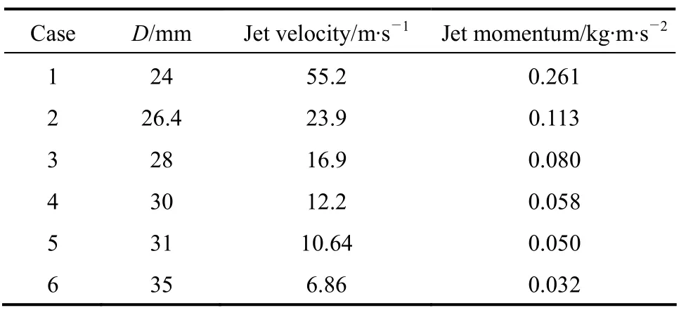
Table 1 Case definition
2.3 Computational conditions and models
The commercial computational software package Fluent 6.3 is used. Full three-dimensional structured grids are constructed with good orthogonality. The final grids for the half model (geometrical symmetry is utilized) are determined to be 400000 cells after checking grid independence results (Fig. 2).

Figure 1 Schematic of furnace for CFD simulation (in unit of mm)

Figure 2 Schematic diagram of CFD mesh
The mixture is assumed to obey the ideal gas law.The specific heat of the mixture is a function of temperature (piecewise-polynomial) [14]. Inlet, outlet and wall boundary conditions of the computational domain are set as constant velocity, constant pressure(static pressure=101 kPa) and constant temperature boundaries, respectively. The heat exchangers are defined as a temperature (400 K) boundary and the total heat flux (convection and radiation) through the heat exchangers is checked after convergence (approximately 3.4 kW).
The standardk-εmodel with the standard wall function is used for modelling the turbulent flow. The turbulent Schmidt number (Sct) used is 0.7 [19]. The eddy dissipation concept (EDC) with two-step chemical kinetic mechanisms for CH4and one-step mechanism for C2H6is applied [20]. The present calculation adopts thein-situadaptive tabulation (ISAT) model of Pope [21] to reduce the computational cost of time integration. The discrete ordinate (DO) radiation model [22] with weighted sum of gray gas model(WSGGM) to model the gas emissivity is applied for radiation. The SIMPLE algorithm was used for pressure velocity coupling. The NOxformation is computed by taking equilibrium conditions for the reaction O22O [18]. The formation rate is given by


A second-order discretization scheme is used to solve all governing equations. Convergence is obtained when the residuals are less than 10-6for energy and DO intensity and 10-3for all other variables. The outlet temperature is monitored and its variation within 1 K is allowed for convergence of the solution.
3 RESULTS AND DISCUSSION
Figure 3 shows contours of thez-component of the mean velocity,vz(m·s-1), in the centralxz-plane(upper) and thexy-plane atz=400 mm (lower). To see the global flow structure more clearly, the velocity vector field for Case 1 is presented in Fig. 4. Evidently,the furnace flow patterns are similar for all the cases:i.e., they are all characterised by a central upward (initially fuel-air mixture) flow (vz>0), which is reversed by the furnace ceiling (top wall), and side downward flue-gas flows mainly at four corners (vz<0). In the present furnace modelled, the upward mass flow rate(Pup) must be equal to the downward mass flow rate(Pdown) at eachxycross-section above the burner exit,i.e.,Pup(z)=Pdown(z). So, the recirculation rate of the flue gas can be measured by the central upward mass flow rate,viz.

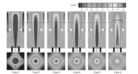
Figure 3 Contours of the z-component mean velocity vz (m·s-1) in the xz-plane (y=0, upper) and xy-plane at z=400 mm(lower)
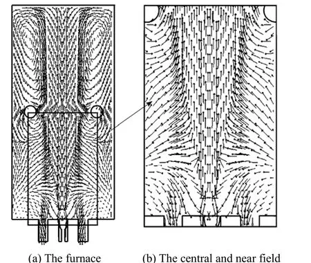
Figure 4 Velocity vectors in the furnace and the central and near field (Case 1: D=24 mm)
whereA(z) means the area withvz>0. For the same inlet mass flow rate of fuel and air, the higher value ofPup(z) reflects the more recirculation of the flue gas,i.e.Pdown(z). Thus, Fig. 3 clearly demonstrates that the most dynamical and strongest recirculation occurs in Case 1, whose momentum rateJois highest. AsJodecreases from Case 1 to Case 6,Pupreduces significantly (and thus the dark-coloured area for contours ofvz≥6 m·s-1in the cross-section ofz=400 mm becomes smaller). As a result, the recirculation of flue gases weakens and, accordingly, the mixing rate between the reactants and combustion products decreases greatly.
The intense dilution of the reactants by hot flue gas recirculation is considered as one of the vital requirements for achieving MILD combustion. The recirculation controls the temperature and the local oxygen concentration and hence the characteristics of reaction zone. Better mixing between hot products and air is required for minimizing hot spots and obtaining thermally uniform field, which leads to lower levels of NOxand CO emissions.
The relative exhaust gas recirculation rate,Kv,may be defined as the ratio of mass flow rate of entrained gases (i.e., the total mass flow rate through the effective jet cross-section subtracting the mass flow rate of inlet air-fuel mixture) to that of the inlet air-fuel mixture,i.e.,

The upward mass flow rates (Pup) and the relative recirculation rates (Kv) for all the cases were calculated from their CFD data and using Eqs. (1) and (2). Fig. 5 shows the dependence ofKvon the inlet momentum rateJo(kg·m·s-2) at fivexy-planes ofz=100, 200,300, 400 and 500 mm.
Clearly, as the jet proceeds upwards,i.e.zincreases, more combustion products are entrained into the upcoming mixture jet and thusKvis increased.Also evidently in Fig. 5 (a), increasingJoby reducingD(nozzle diameter) enhances the recirculation of flue gases and thus increasesKvat eachxy-plane. Such a variation of theJo-dependent recirculation is expected to cause switching between the MILD and conventional combustion modes. Indeed, this is the case, as illustrated by Fig. 6. Apparently, Cases 1-3 have more uniform temperature (~1400 K) distributions than do cases 4-6 (~2100 K). It is obvious as well that Cases 4-6 correspond to the conventional combustion mode with visible flames in the central region of the furnace while Cases 1-3 represent the MILD mode. High local flame temperatures in the central region of Cases 4-6 cause significantly more thermal NOxformations,relative to the MILD combustion of Cases 1-3 where nearly zero emissions of NOxare produced (Fig. 7).So it is deduced thatJcr≈0.07 (kg·m·s-2), the average over Cases 3 and 4, can be considered as the critical value of the inlet momentum rate [indicated in Fig. 5(a)] for this premixing arrangement and the furnace shown in Fig. 1. Hence, whenJo<Jcr, the MILD combustion generally does not take place.

Figure 5 Exhaust gas recirculation rate (Kv)

Figure 6 Temperature contours (K) on the central xz-plane (y=0)
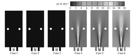
Figure 7 Contours of the thermal NO production [μL·(L dry)-1] in the central xz-plane (y=0)
For Cases 1-3, high recirculation of rich-CO2(≈9%) flue gas dilutes reactants by strong mixing so that the volume (or mole) fraction of O2is rapidly decreased to a very low level (≈5%, see Fig. 8) before reaction happens. As a result, when oxidation occurs,its reaction rate is considerably smaller than normal combustion. For Cases 4-6, low flue-gas recirculation(Kv=0.6-1.8) cannot produce any sufficiently strong mixing of combustion products with reactants so that the initially-high oxygen cannot be well diluted for MILD combustion to occur. On the other hand, due to low inlet speed and the presence of a central circulation attached to the bluff body, the upcoming reactant mixture is heated up so that high temperature and rich oxygen enable oxidation taking place rapidly. It is thus seen in Figs. 8 & 9 that traditional combustion occurs in the small horn-like zone attaching to the burner,where all the premixed natural gas is burnt out with oxygen to produce CO2and H2O. Consequently, the volume fractions of O2and CO2are nearly 4% and 9%in the rest of the furnace (Figs. 8 & 9). In addition, the global exhaust CO emissions for Cases 1 to 6 were obtained to be 20, 20, 2, 5, 21 and 2 μL·(L dry)-1, respectively. This indicates that all the combustion simulated is nearly complete no matter whether it is in the MILD or conventional regime.
Furthermore, several interesting observations can be made from Figs. 6, 8 & 9. Very small differences occur between spatial distributions of temperature, O2and CO2concentrations for Cases 4-6. By comparison,significant differences can be seen between the same distributions for Cases 1-3. It is thus suggested that the effect of the inlet momentum rate is less significant on conventional combustion than on MILD combustion. Nevertheless, this was not found in our previous investigation on the non-premixed combustion [13].
Figure 10 shows where the presentKvis locatedin the diagram of the stability limits made by Wünning & Wünning [3] for different non-premixed combustion modes in a furnace operating under exhaust gas recirculation mode. Here Kvis presented against Tav, the temperature averaged over the effective jet cross-section. This diagram quantifies the influence of Kvon the combustion process. For Tavexceeds the temperature of auto-ignition (≈800°C), as Kvincreases beyond its critical value (depending on Tav), the combustion process develops from the conventional mode to the MILD mode. This means that Kvplays a significant role in determining the combustion mode.This also indicates that the inlet air-fuel momentum rate Jocontrols the combustion mode since the magnitude of Kvis determined by Jo, see Fig. 5 (a). The growth of Joenables Kvto increase beyond the boundaries of stable flame and MILD combustion,and thus the combustion process switch from the former to the latter. However, the stability limit boundaries for the present cases should be different from those obtained by Wünning & Wünning [3], whose diagram may apply only precisely for the non-premixed combustion. Apparently, most of the data points for Cases 2-5 are located in the unstable flame region,while those for Cases 1 and 6 are placed well within MILD and stable flame regimes respectively. Note that the unstable flame cannot be simulated by the present CFD work.

Figure 8 Contours of the mole fraction of O2 in the central xz-plane

Figure 9 Contours of the mole fraction of CO2 in the central xz-plane
4 CONCLUSIONS
This study has numerically investigated the influence of the inlet momentum rate of the premixed fuel-air jet on combustion process in a 10 kW recuperative combustor. The present simulations reveal that the recirculation is strengthened as the inlet momentum rate increases. It is also found that the premixed MILD combustion can be established when the internal recirculation of flue gases is sufficiently strong. Similar to the non-premixed combustion examined by both experiments and numerical simulations [13], the premixed combustion investigated presently is also found to have a critical value of the inlet momentum rate below which the premixed MILD combustion does not occur. Of interest to note, as well,the momentum rate imposes less significant influence on the conventional combustion than on the MILD combustion. This however may not apply for the non-premixed combustion performed in the same furnace, as indicated by our previous investigation [13].
ACKNOWLEDGEMENTS
We thank Dr. B.B. Dally, University of Adelaide,for his suggestion on CFD modelling.
NOMENCLATURE
A air mass flow rate, kg·s-1
Aothe annulus tube exit area, m2
D outer diameter of inlet annulus tube, mm
F fuel mass flow rate, kg·s-1
Joinitial momentum rate, kg·m·s-2
Kvexhaust gas recirculation rate
kNIfreaction constant, m3·kmol-1·s-1
Uoinlet jet velocity, m·s-1
vzthe velocity component in the z-direction, m·s-1
ρodensity, kg·m-3
φ equivalence ratio
1 IEA, Energy Technology Perspectives: Scenarios and Strategies to 2050, International Energy Agency, Paris (2006).
2 IPCC, “Working Group II Repont: Impacts, Adaptation and Vulnerability”, In: Climate Change 2007, Cambridge Univ. Press, London(2007).
3 Wünning, J.A., Wünning, J.G., “Flameless oxidation to reduce thermal NO-formation”, Progr. Energy Combust. Sci., 23 (1), 81-94(1997).
4 Cavaliere, A., de Joannon, M., “Mild combustion”, Prog. Energy Combust. Sci., 30 (4), 329-366 (2004).
5 Tsuji, H., Gupta, A., Katsuki, M., High Temperature Air Combustion:From Energy Conservation to Pollution Reduction, CRC Press, F Lorida (2003).
6 Blarino, L., Fantuzzi, M., Malfa, E., Zanusso, U., “Tenova Flexytech burners: Flamesless combustion for very low NOxreheating furnaces”, In: Proceedings of the HITAC Conference, Thailand (2007).
7 Blasiak, W., Yang, W., “Volumetric combustion of coal and biomass in boilers”, In: Proceedings of the HITAC Conference, Thailand(2007).
8 Kunio, Y., “R&D commercialization of innovative waste-to-energy technologies”, In: Proceedings of the HITAC Conference, Thailand(2007).
9 Christo, F.C., Dally, B.B., “Modeling turbulent reacting jets issuing into a hot and diluted coflow”, Combust. Flame, 142 (1/2),117-129(2005).
10 Kim, J.P., Schnell, U., Scheffknecht, G., Benim, A.C., “Numerical modelling of MILD combustion for coal”, Progr. Comput. Fluid Dynam., 7 (6), 337-346 (2007).
11 Yang, W.H., Blasiak, W., “Numerical simulation of properties of a LPG flame with high-temperature air”, Int. J. Therm. Sci., 44 (10),973-985 (2005).
12 Schaffel, N., Mancini, M., Szlek, A., Weber, R., “Mathematical modeling of MILD combustion of pulverized coal”, Combust. Flame,156 (9), 1771-1784 (2009).
13 Mi, J., Li, P., Dally, B.B., Craig, R.A., “Importance of Initial Momentum Rate and Air-Fuel Premixing on MILD Combustion in a Recuperative Furnace”, Energ. Fuel., 23 (11), 5349-5356 (2009).
14 Fluent 6.3 Documentation, Fluent Inc., New Hampshire (2007).
15 Szeg, G.G., Dally, B.B., Nathan, G.J., “Scaling of NOxemissions from a laboratory-scale mild combustion furnace”, Combust. Flame,154 (1/2), 281-295 (2008).
16 Szeg, G.G., Dally, B.B., Nathan, G.J., “Operational characteristics of a parallel jet MILD combustion burner system”, Combust. Flame,156 (2), 429-438 (2009).
17 Dally, B.B., Craig, R.A., Mi, J., “Dependence of flameless combustion on fuel-air injection pattern and their momentum ratio in a recuperative furnace”, In: Proceedings of the 9th Asia-Pacific Int.Symp. on Combustion and Energy Utilization, 35-40 (2008).
18 Turns, S., An Introduction to Combustion: Concepts and Applications, McGraw-Hill, New York (1996).
19 Spalding, D.B., “Concentration fluctuations in a round turbulent free jet”, Chem. Eng. Sci., 26 (1), 95-107 (1971).
20 Westbrook, C.K., Dryer, F.L., “Simplified reaction mechanisms for the oxidation of hydrocarbon fuels in flames”, Combust. Sci. Technol., 27 (1), 31-43 (1981).
21 Pope, S., “Computationally efficient implementation of combustion chemistry using in situ adaptive tabulation”, Combust. Theor. Model.,1 (1), 41-63 (1997).
22 Chui, E., Raithby, G., “Computation of radiant heat transfer on a nonorthogonal mesh using the finite-volume method”, Numer. Heat Transfer B-Fund., 23 (3), 269-288 (1993).
